Ultrasonic thermal ablation probe

a technology of thermal ablation probe and ultrasonic radiation, which is applied in the field of ultrasonic tissue treatment, can solve the problems of increasing the maximum acoustic power of the probe, and achieve the effects of increasing the acoustic power, limiting the bulk of the probe, and improving the efficiency of the transducer

Active Publication Date: 2021-10-05
CARTHERA SAS
View PDF21 Cites 0 Cited by
  • Summary
  • Abstract
  • Description
  • Claims
  • Application Information

AI Technical Summary

Benefits of technology

[0037]Thus, the invention offers the possibility of having a cooling by using a cooling fluid—such as water—on the rear face(s) of the transducer(s) while retaining an electro-acoustic conversion efficiency as high as that of intra-tissue applicators of which the rear face is cooled by air.
[0038]This makes it possible to obtain an interstitial probe for treatment by hyperthermia with increased effectiveness, which allows its miniaturization. This new arrangement allows the effectiveness of the probe to be maximized in terms:
[0041]The optimizations applied to the probe according to the invention allow the acceleration of the duration of the treatments performed. In fact, the fact of cooling the transducers with a cooling fluid allows an increase in the duration of activation of the transducers (in particular, it is not necessary to deactivate the transducers for a certain period to allow their cooling). Moreover, effective cooling of the transducers allows an increase in the maximum acoustic power that the probe can emit, which is mainly limited by the overheating of the piezoelectric element bringing about its deterioration. Increased acoustic power emitted by the probe allows a reduction in the treatment time and the treatment of a larger volume.
[0067]The optimization of the thickness of the layer of cooling fluid allows, on the one hand, limiting the bulk of the probe, and on the other hand improving the efficiency of the transducers, and therefore increasing the acoustic power that they can emit to accelerate treatment and increase the depth of penetration.

Problems solved by technology

Moreover, effective cooling of the transducers allows an increase in the maximum acoustic power that the probe can emit, which is mainly limited by the overheating of the piezoelectric element bringing about its deterioration.

Method used


Image

  • Ultrasonic thermal ablation probe
  • Ultrasonic thermal ablation probe
  • Ultrasonic thermal ablation probe

Examples


Embodiment Construction

1. General

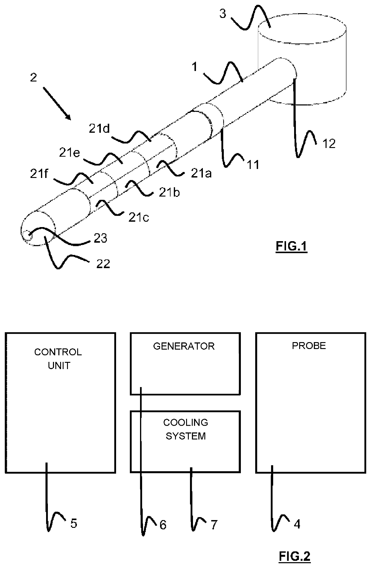
[0074]With reference to FIG. 1, one example of probe for the hyperthermia treatment of a target zone is illustrated. The probe—or applicator—is designed to be introduced into the body of a patient to allow the treatment of the target zone. The diameter of the probe is preferably less than 5 mm (in particular equal to 3.5 mm) to facilitate its introduction into the interior of the patient interstitially or through a catheter.

[0075]The probe comprises:[0076]a flexible longitudinal body 1 with a generally cylindrical shape,[0077]an active portion 2 mounted at a distal end 11 of the body 1, the active portion 2 including one (or more) ultrasonic transducer(s) 21a-21f, [0078]a junction box 3 mounted at a proximal end 12 of the body 1 to electrically connect the active portion to a remote control unit allowing control of the transducer(s) 21a-21f.

[0079]1.1. Body

[0080]The body 1 can be composed of a flexible sleeve made in a material selected for its non-toxic and high tolerance...


PUM


Abstract

The present invention relates to an ultrasonic probe for heating, internally, an ultrasonically absorbent target medium, the probe comprising: at least one piezoelectric transducer (21) having a front face (212) intended to be positioned facing the target medium and a back face (211) opposite the front face (212), the transducer being able to emit at least one primary wave emanating from its front face and at least one secondary wave emanating from its back face, the probe being noteworthy in that it furthermore comprises: a reflector (24) facing the back face (211) of the transducer (21), the reflector (24) being suitable for reflecting the secondary wave emitted by the transducer (21); and a cooling-fluid layer (25) between the transducer (21) and the reflector (24).

Description

CROSS-REFERENCE TO RELATED APPLICATIONS[0001]This application is a national phase filing under 35 U.S.C. § 371 of International Application No. PCT / EP2017 / 059047 filed on Apr. 14, 2017, which claims benefit of priority from French Patent Application No. 1653377 filed Apr. 15, 2016, the contents of which are hereby incorporated by reference in their entirety.FIELD OF THE INVENTION[0002]The present invention relates to the general technical field of ultrasonic tissue treatment, and in particular the technical field of ultrasonic emission devices.[0003]More precisely, the present invention relates to interstitial probes for the treatment by hyperthermia of a target zone—such as a malignant tumor—localized using high-intensity ultrasonic waves.BACKGROUND OF THE INVENTION1. General[0004]Therapeutic ultrasound is used today in numerous applications, in particular to allow the ablation of undesirable tissue or tumors.[0005]An external ultrasonic treatment device has already been proposed. ...

Claims


Application Information

Patent Timeline
Patent Type & Authority Patents(United States)
IPC IPC(8): A61B5/05A61N7/02B06B1/06A61B17/22A61N7/00
CPCA61N7/02B06B1/0655A61B17/2202A61B2017/22024A61N2007/0047A61N2007/0069A61N2007/025
Inventor CANNEY, MICHAELBOUCHOUX, GUILLAUMEVIGNOT, ALEXANDRELACOSTE, FRANCOIS
Owner CARTHERA SAS
Why Eureka
Try Eureka