Image forming apparatus

a technology of image forming apparatus and forming tube, which is applied in the field of image forming tube, can solve the problems of insufficient precision, inability to grasp the accurate increase in the amount of color material, so as to prevent image defects, prevent image defects, and improve the effect of fixation

Inactive Publication Date: 2013-04-18
CANON KK
View PDF7 Cites 12 Cited by
  • Summary
  • Abstract
  • Description
  • Claims
  • Application Information

AI Technical Summary

Benefits of technology

[0007]The present invention enables realization of an image forming apparatus that forms a test pattern for controlling the amount of color material with taking spectral characteristics of colors into consideration, suppresses an increase in the color material amount, and prevents image defects such as spattering, poor fixation related to granularity of color material, or the like.

Problems solved by technology

However, there are the following problems in the conventional techniques.
With a conventional method for determining the maximum amount of color material using density, since the resolution particularly in high density portions is insufficient due to a relationship between the spectral reflectance of color material and the spectral sensitivity of a reader, the precision is not sufficient.
As shown in reference numeral 1101 of FIG. 11, even if the amount of color material changes, spectral characteristics in the maximum density portion have change little in the detected spectral wavelength ranges, and density values vary due to lifting of a test chart or influence of various types of noises, and thus it has not been possible to grasp the accurate amount of color material.
As a result, variation occurs in the result of correcting the maximum amount of color material, leading to an increase in the amount of color material, and spattering, poor granularity, and poor fixation of color material.

Method used


Image

  • Image forming apparatus
  • Image forming apparatus
  • Image forming apparatus

Examples


first embodiment

Configuration of Image Forming Apparatus

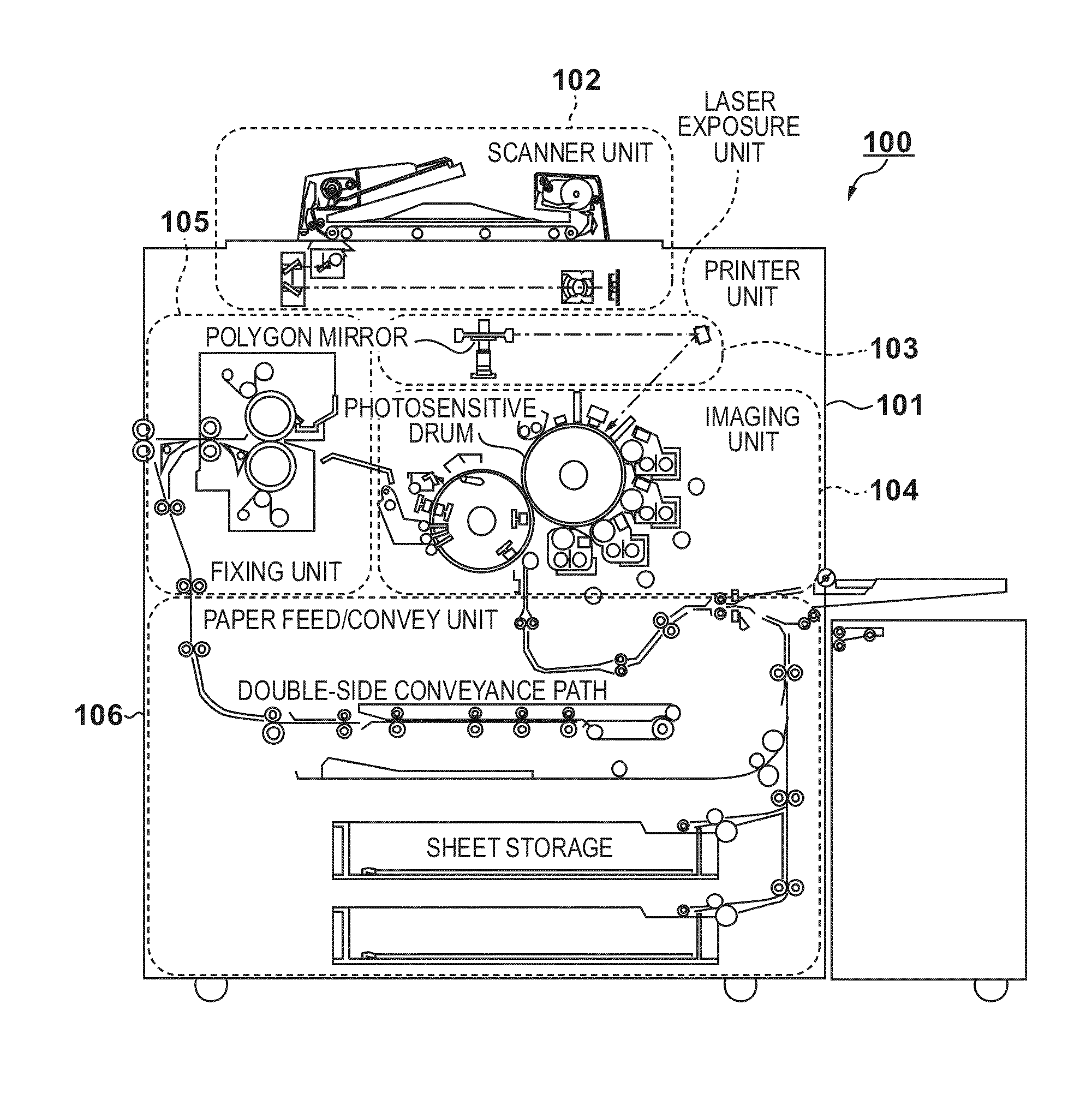
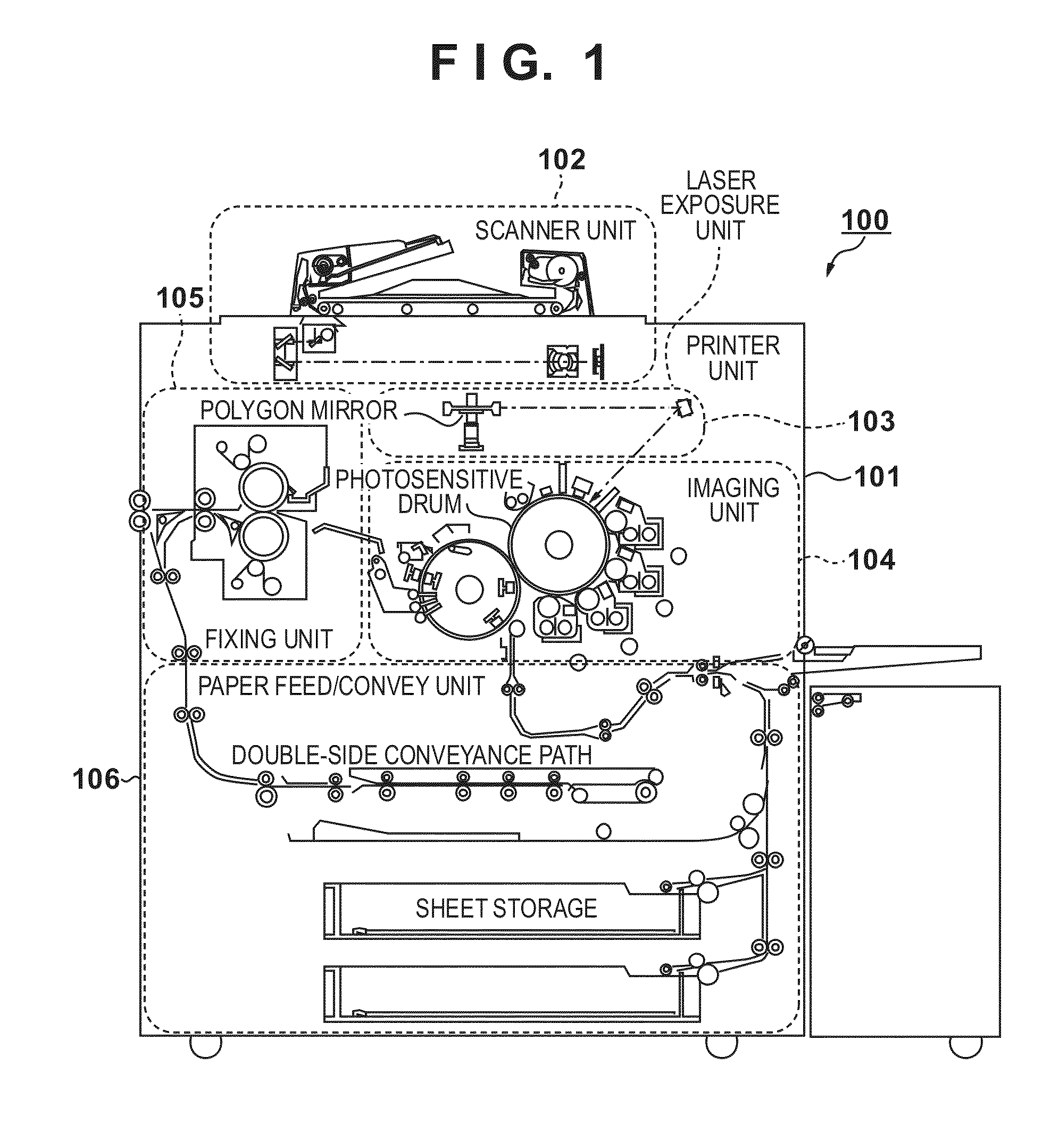
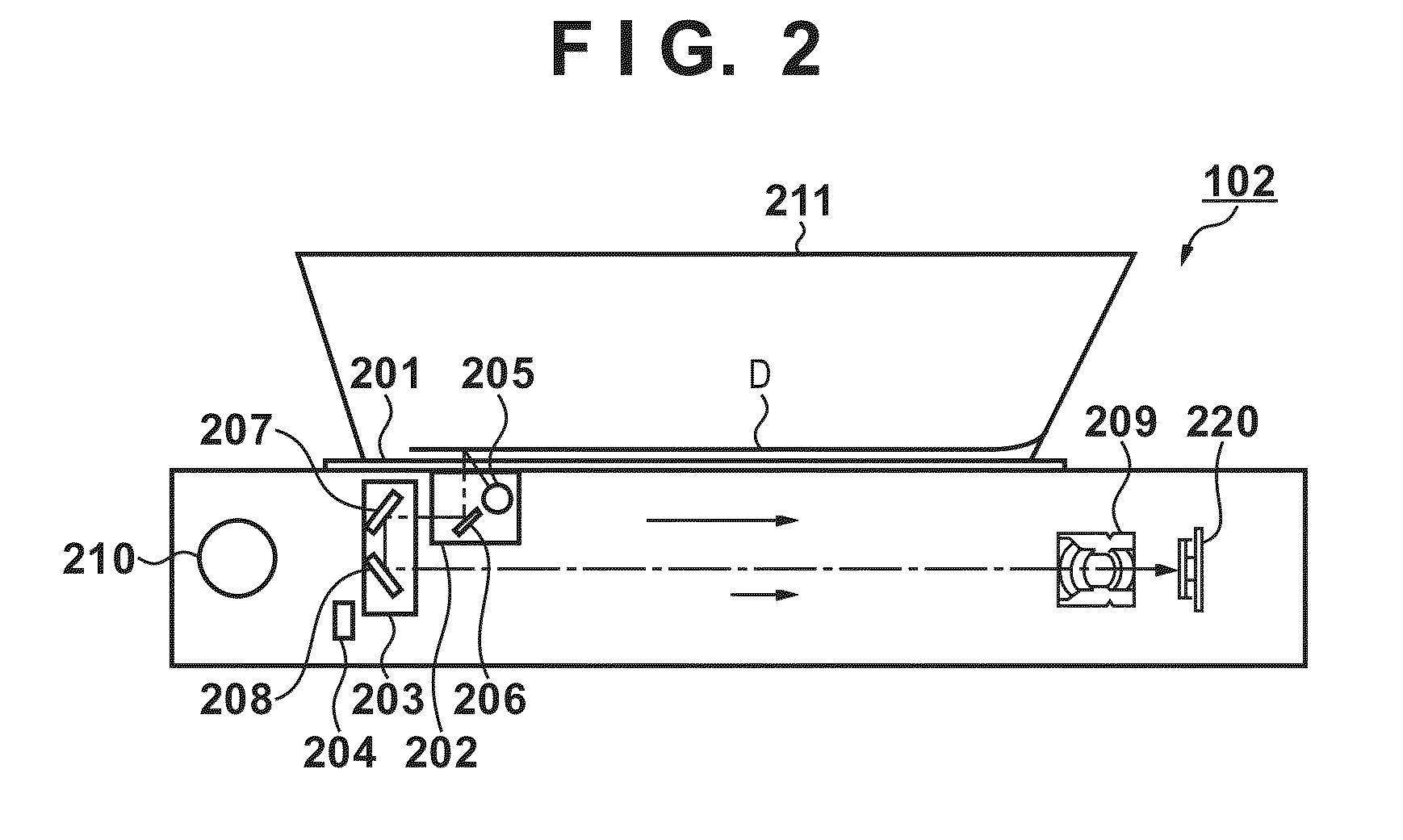
[0030]First, a configuration of an MFP 100 having an electrophotographic printer unit 101 and a scanner unit 102 is described below with reference to FIG. 1. Here, the description is given using the MFP (multi-function peripheral) 100 as one example of image forming apparatuses. The printer unit 101 is configured with a laser exposure unit 103, an imaging unit 104, a fixing unit 105, a paper feed / convey unit 106, and a printer control unit for controlling these units. The scanner unit 102 reads an image of the original optically by irradiating the original placed on a platen with light, and converts the image into a RGB color electrical signal to form image data. The resolution of the scanner unit 102 is 600 dpi.

[0031]The laser exposure unit 103 causes light such as laser light or the like that is modulated according to image data to be incident on a rotary multifaceted mirror (polygon mirror) that rotates at an equiangular velocity, and irrad...

second embodiment

[0093]Hereinafter, a second embodiment of the present invention is described. In the above-described first embodiment, it is assumed that a standard paper sheet (for example, plain paper CS-814 made by Canon Corporation) is the medium for calculating the maximum color material amount. Using the standard paper sheet, first, cyan is corrected with the density of yellow as a reference, and magenta is corrected after cyan is adjusted in order to detect the hue mixed with another color. Although a conventional method is used since the resolution in relatively high density portions is maintained with yellow, it is possible that yellow is influenced by variation between pages or in-plane uniformity of the printer unit. Thus, in the present embodiment, CAL-dedicated paper serving as paper for the automatic gradation correction is used in order to remove variation of the printer unit.

[0094]For example, at the time of cyan color material amount correction, Cannon PPC color (colored paper) 64 ...

third embodiment

[0095]Hereinafter, a third embodiment of the present invention is described with reference to FIG. 17. In the above-mentioned second embodiment, correction is performed using a plurality of colored paper. Since there are issues in usability, a configuration is changed to one paper sheet. FIG. 17 shows CAL-dedicated paper used in the present embodiment.

[0096]A pattern image of yellow and a pattern image of cyan whose density is checked to be a prescribed density (0.48±0.01) are printed on A3 size paper, and at the time of the color material correction of the printer unit 101, LPWs of cyan and magenta are adjusted using this paper. It is possible to reduce output of three paper sheets, which is described in the above-mentioned first embodiment, to one sheet by securing a space where a test chart of black and yellow shown in FIG. 9 can be printed on the lower side of this CAL-dedicated paper. Note that the present CAL paper is not provided with grid lines. Also, as an innovation of the...


PUM


Abstract

The present invention provides an image forming apparatus that forms a test pattern for controlling the amount of color material, suppresses increase of the color material amount, and prevents image defects such as spattering, poor fixation due to granularity, or the like. To accomplish this, the image forming apparatus forms a test pattern on printing material using color material of a plurality of colors, reads the formed test pattern, and controls the color material amount of each color by changing an image forming condition in accordance with a result of the reading. Note that the image forming apparatus forms a mixed pattern image using color material of a plurality of chromatic colors, and controls the amount of color material of a single color based on the mixed pattern image.

Description

BACKGROUND OF THE INVENTION[0001]1. Field of the Invention[0002]The present invention relates to an image forming apparatus that prints color material such as toner or the like on a paper sheet.[0003]2. Description of the Related Art[0004]With an image forming apparatus in which an electrophotographic method is adopted, an image carrier called a photosensitive body is charged by a primary charger, and a latent image is formed on the image carrier by an optical system such as a laser or the like. The latent image is developed by a development unit having color material called toner on the image carrier using the toner. Toner that has been developed and held on the image carrier is transferred on a paper sheet by one or two transfers, and fixed to the paper sheet by a thermal fixing apparatus. In a basic printing process of an electrophotographic method, since the above-mentioned electrostatic development is used, the process is easily influenced by temperature and humidity. Therefore...

Claims


Application Information

Patent Timeline
Patent Type & Authority Applications(United States)
IPC IPC(8): H04N1/60
CPCH04N1/605
Inventor ITAGAKI, TOMOHISA
Owner CANON KK
Why Eureka
Try Eureka