Surface cleaning apparatus

Active Publication Date: 2013-09-05
OMACHRON INTPROP
View PDF32 Cites 50 Cited by
  • Summary
  • Abstract
  • Description
  • Claims
  • Application Information

AI Technical Summary

Benefits of technology

[0149]A further advantage of this configuration is that the amount of dirt particles that collect on the support surface may be reduced and the amount of dirt particles re-

Problems solved by technology

The discontinuity may disrupt the flow of the dirty air flowing along the inner surface of the sidewall, which may help d

Method used


Image

  • Surface cleaning apparatus
  • Surface cleaning apparatus
  • Surface cleaning apparatus

Examples


Embodiment Construction

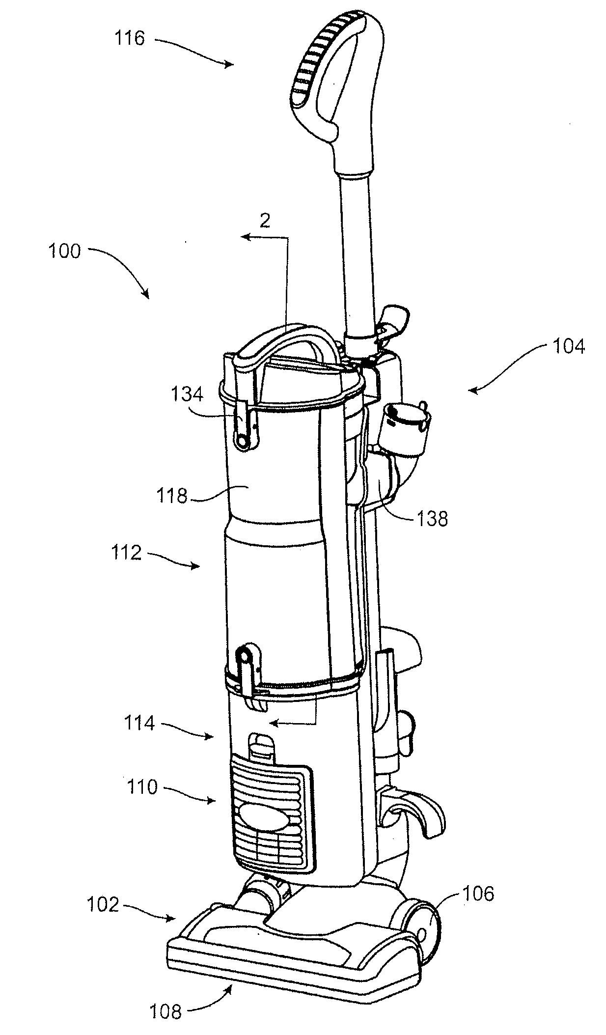
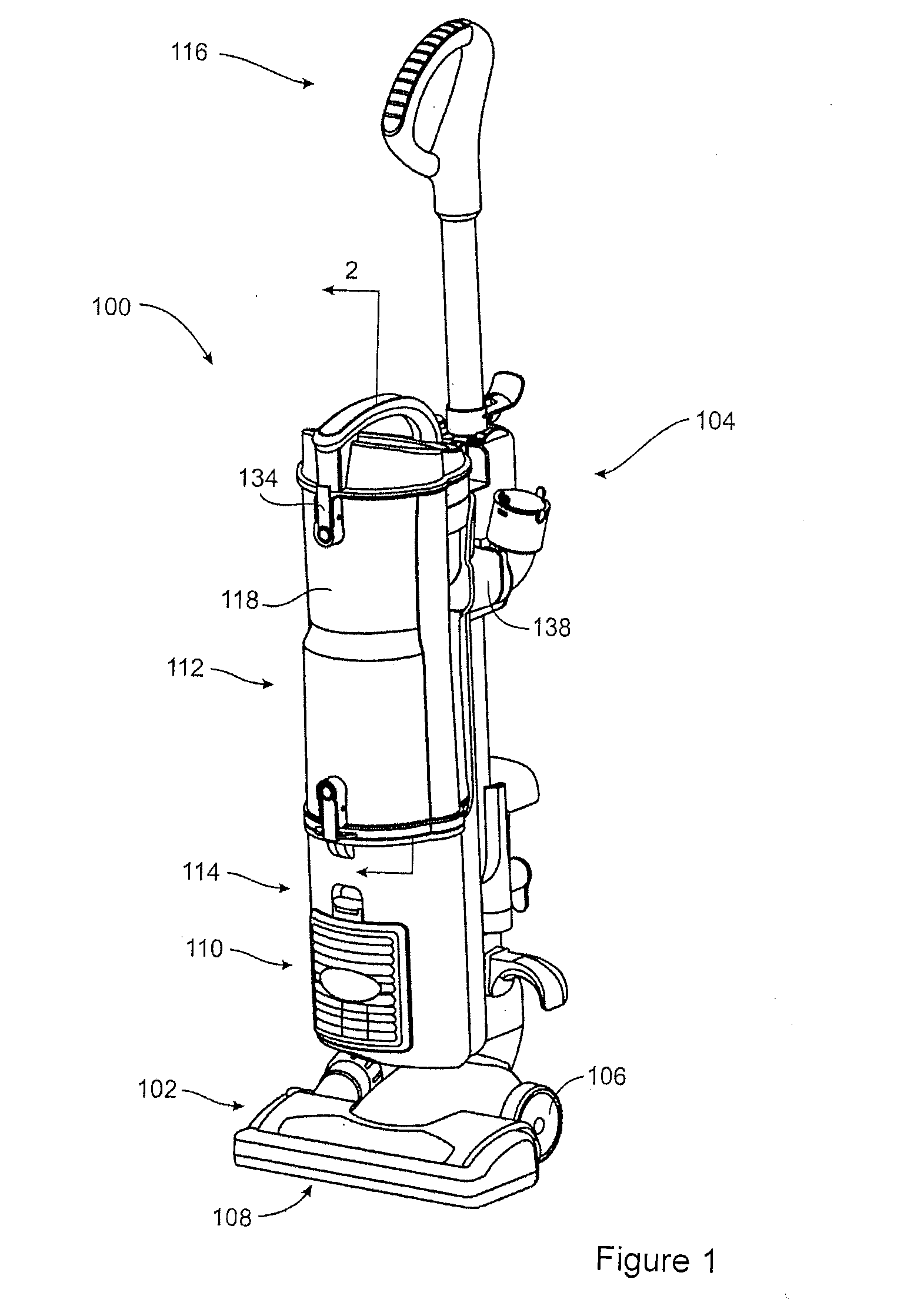
[0188]Referring to FIG. 1, an embodiment of a surface cleaning apparatus 100 is shown. In the embodiment illustrated, the surface cleaning apparatus 100 is an upright surface cleaning apparatus. In alternate embodiments, the surface cleaning apparatus may be another suitable type of surface cleaning apparatus, including, for example, a hand vacuum, a canister vacuum cleaner, a stick vac, a wet-dry vacuum cleaner and a carpet extractor.

General Overview

[0189]As exemplified in FIG. 1, a surface cleaning apparatus 100 includes a surface cleaning head 102 and an upper section 104.

[0190]The surface cleaning head 102 may be any suitable type of cleaning apparatus, including, for example a powered cleaning head having a rotating brush and a brushless cleaning head. The surface cleaning head 102 may be of any suitable configuration and may include at least one wheel or other rolling support to contact the surface being cleaned.

[0191]In the illustrated example the surface cleaning head 102 in...


PUM

PropertyMeasurementUnit
Lengthaaaaaaaaaa
Areaaaaaaaaaaa

Abstract

A surface cleaning apparatus comprises an air flow passage extending from a dirty air inlet to a clean air outlet and a suction motor. The surface cleaning apparatus may also comprise a cyclone chamber provided in the air flow passage. The cyclone chamber may comprise a cyclone air inlet, a cyclone air outlet and a dirt outlet. The surface cleaning apparatus may comprise a dirt collection chamber having a dirt inlet, a dirt collection chamber first end, an opposed dirt collection chamber second end and a longitudinally extending sidewall. Various design improvements are provided.

Description

RELATED APPLICATIONS[0001]This application claims the benefit of 35 USC 119 based on the priority of co-pending U.S. patent application Ser. No. 13 / 040,711 filed Mar. 4, 2011, U.S. patent application Ser. No. 13 / 040,955 filed Mar. 4, 2011, U.S. patent application Ser. No. 13 / 040,751 filed Mar. 4, 2011, U.S. patent application Ser. No. 13 / 040,768 filed Mar. 4, 2011, U.S. patent application Ser. No. 13 / 040,731 filed Mar. 4, 2011, and U.S. patent application Ser. No. 13 / 040,934 filed Mar. 4, 2011, and each of those applications being incorporated herein in their entirety by reference.FIELD[0002]The disclosure relates to surface cleaning apparatuses, such as vacuum cleaners.INTRODUCTION[0003]Various constructions for surface cleaning apparatuses, such as vacuum cleaners, are known. Currently, many surface cleaning apparatuses are constructed using at least one cyclonic cleaning stage. Air is drawn into the vacuum cleaners through a dirty air inlet and conveyed to a cyclone inlet. The ro...

Claims


Application Information

Patent Timeline
IPC IPC(8): A47L9/16
CPCA47L9/1683B01D45/12B04C2009/004B01D50/002B04C5/08B04C5/04B01D50/20A47L9/1658A47L9/1608B01D45/16B01D46/00B04C5/00B04C11/00
Inventor CONRAD, WAYNE ERNEST
Owner OMACHRON INTPROP
Why Eureka
Try Eureka