Oil mist eliminator

Inactive Publication Date: 2003-01-02
KURAKO
View PDF0 Cites 8 Cited by
  • Summary
  • Abstract
  • Description
  • Claims
  • Application Information

AI Technical Summary

Benefits of technology

0005] In view of the above insufficiency, the present invention has been accomplished to provide an oil mist eliminator which is capable of separating the oil mist successfully and efficiently. The oil mist eliminator in accordance with the present invention includes a casing with an inlet and an outlet, and an impeller which is accommodated within the casing and is driven to rotate about a rotation axis for drawing an oil-contaminated air through the inlet and discharging a clean air removed of the oil mist out through the outlet. The impeller is composed of a rear disc provided at its center with a hub for receiving a rotating shaft in registration with the rotation axis, a front disc spaced forwardly of the rear disc in a coaxial relation thereto. The front disc has a

Problems solved by technology

With this arrangement, however, there remains a problem that the air (indicated by arrows in FIG. 8) drawn through the center opening and guided radially outwardly adjacent along the rear disc 50P may partially escape rearwards past the outer circumferen

Method used


Image

  • Oil mist eliminator
  • Oil mist eliminator
  • Oil mist eliminator

Examples


Embodiment Construction

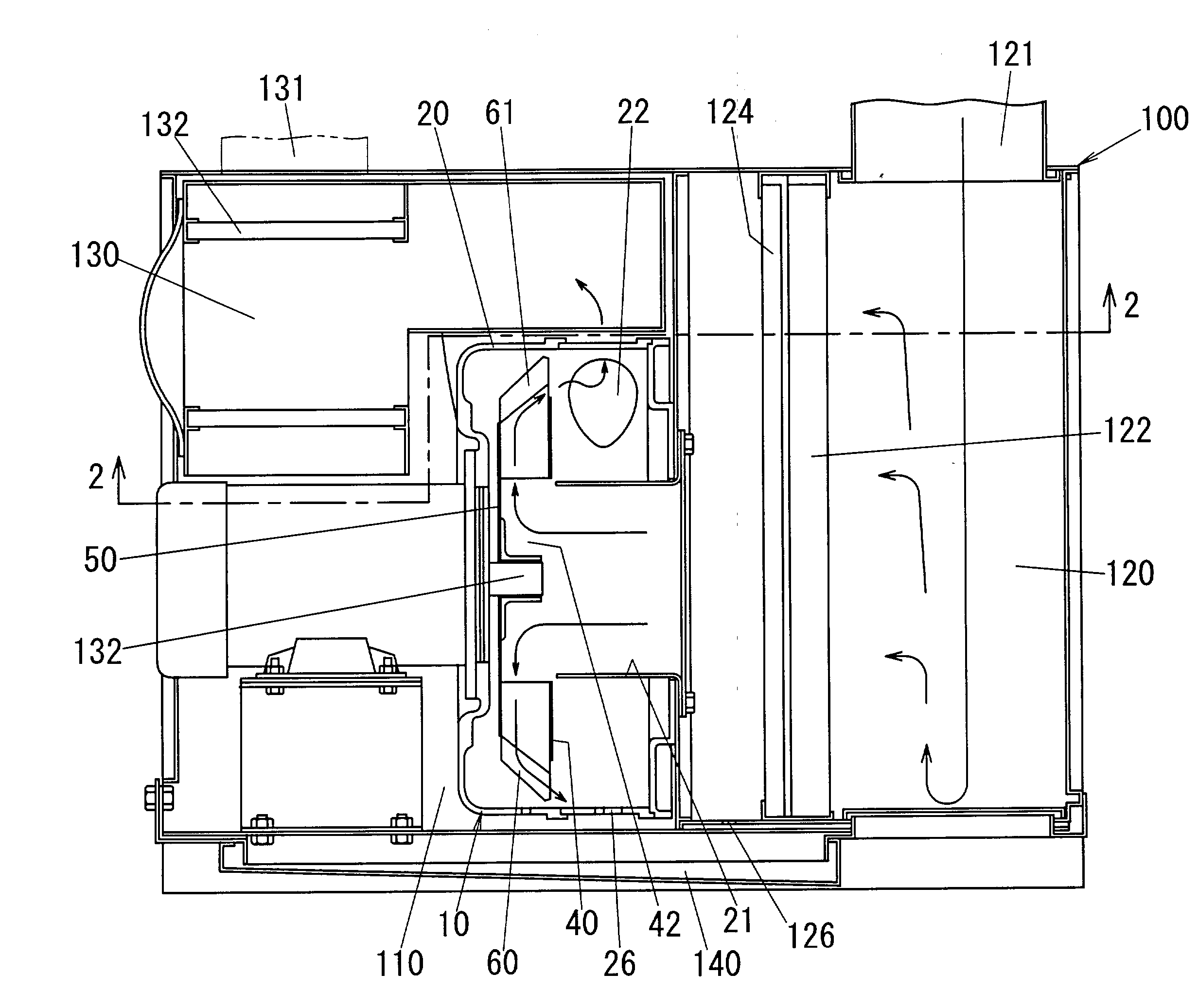
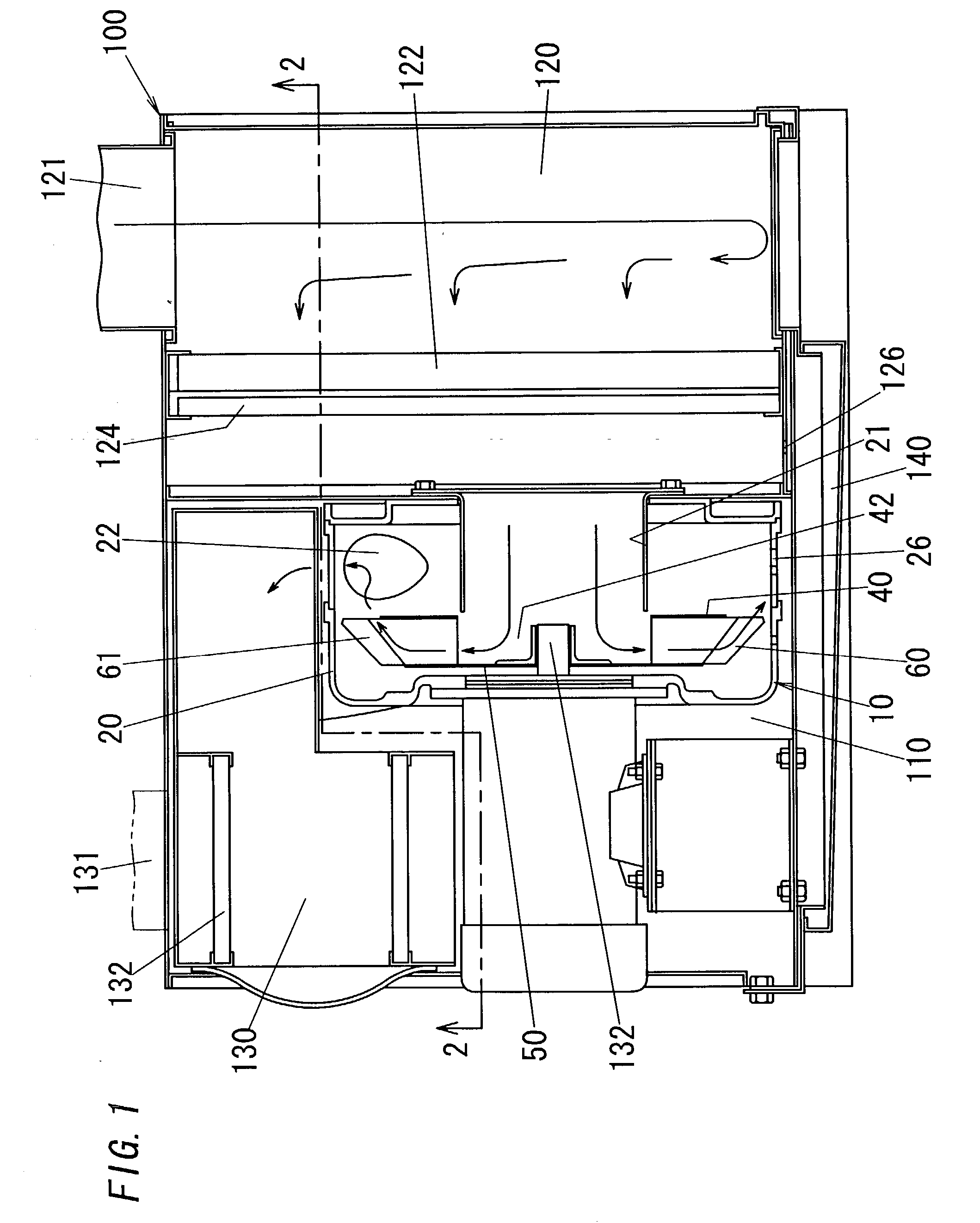
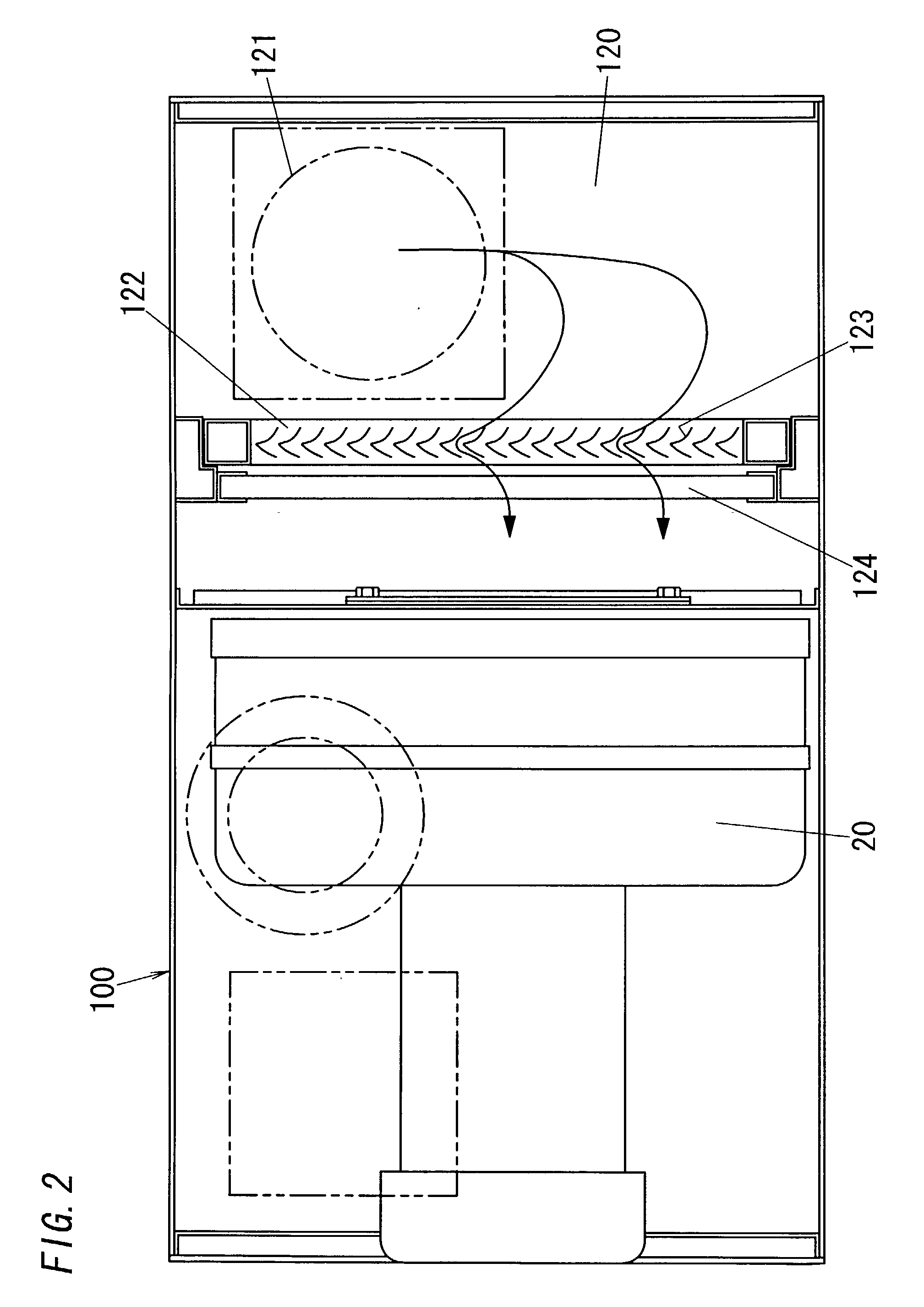
[0019] Referring now to FIGS. 1 and 2, there is shown an oil recovery system incorporating an oil mist eliminator 10 in accordance with a preferred embodiment of the present invention. The system is adapted to be installed in a machine factory where lathes or the like cutting tools are running with an attendant creation of an oil mist, i.e., tiny oil particles spread in the atmosphere, in order to separate the oil particles from the atmosphere and collect thus separated oils for realizing a clean room environment. The system includes a housing 100 having a center chamber 110 for mounting therein the oil mist eliminator 10 which generates a forded air flow from an intake port 121 to an exhaust port 131. The housing 100 further includes a pre-treatment chamber 120 upstream of the eliminator 10 for collecting the oil-contaminated air, a silencing room 130 downstream of the eliminator for muffling a sound of driving the eliminator and at the same time filtering out minute oil particles ...


PUM

PropertyMeasurementUnit
Widthaaaaaaaaaa
Efficiencyaaaaaaaaaa
Distanceaaaaaaaaaa

Abstract

An oil mist eliminator includes an impeller rotating about its axis in one direction within a casing having an inlet and an outlet. The impeller includes a plurality of circumferentially spaced blades held between front and rear discs. The front disc has a center opening for introducing an oil-contaminated air. Each blade is composed of an inner fin extending in a radial direction and an outer fin bent from the inner fin for deflecting the air proceeding between the adjacent inner fins in a forward direction, thereby creating a forced air flow for introducing the air axially from the front opening, guiding it radially between the discs, and venting it axially forwardly in a front-in and front-out fashion. Thus, even a portion of the air being guided immediately along the rear disc can be successfully deflected for collision against the outer fins without fail, maximizing oil separation efficiency.

Description

[0001] 1. Field of the Invention[0002] The present invention is directed to an oil mist eliminator for removing oil mist from a contaminated air and discharge a clean air removed of the oil mist, and more particularly to such an oil eliminator using an impeller which diverts an air flow for separating the oil mist from the contaminated air.[0003] 2. Description of the Prior Art[0004] U.S. Pat. No. 5,207,809 discloses an oil mist eliminator using an impeller or fan for separating the oil mist from an oil-contaminated air while changing flow directions. The oil eliminator includes a casing with an inlet and an outlet, and an impeller which is accommodated within the casing and is driven to rotate about a rotation axis of the impeller for drawing the contaminated air from the inlet and discharge a clean air removed of the oil mist out through the outlet. The impeller is of a front-in and rear-out type which draws the air from a front opening of the impeller and vents the clear air rear...

Claims


Application Information

Patent Timeline
IPC IPC(8): F04D29/30B01D45/14B01D49/00B23Q11/00
CPCB01D45/14B23Q11/0057B01D49/00
Inventor HIGASHINO, TOSHIHIROSHIMAKAWA, KEIJI
Owner KURAKO
Why Eureka
Try Eureka