Separation of fibre pulp suspensions containing relatively heavy contaminants

a technology of fibre pulp suspension and hydrocyclone unit, which is applied in the direction of solid separation, textiles and paper, paper material treatment, etc., can solve the problems of negatively affecting the separation efficiency of the fibre network, and achieve the effects of enhancing separation efficiency, reducing energy consumption, and increasing production capacity

Active Publication Date: 2008-07-29
GLV FINANCE HUNGARY KFT +1
View PDF16 Cites 12 Cited by
  • Summary
  • Abstract
  • Description
  • Claims
  • Application Information

AI Technical Summary

Benefits of technology

[0005]The object of the present invention is to provide a hydrocyclone unit for separating a fibre pulp suspension containing relatively heavy contaminants, which has an increased production capacity, lower energy consumption and enhanced separation efficiency as compared with the conventional hydrocyclone described above.
[0006]Accordingly, the present invention provides a hydrocyclone unit for separating a fibre pulp suspension containing relatively heavy contaminants, the hydrocyclone unit comprising a housing forming an elongate tapering separation chamber having a base end and an apex end, at least one suspension inlet member on the housing designed to feed the suspension to be separated tangentially into the separation chamber at the base end thereof, such that the incoming suspension forms a vortex, in which the heavy contaminants are pulled by centrifugal forces radially outwardly and the fibres are pushed by drag forces radially inwardly, whereby a central fraction of the suspension substantially containing fibres is created centrally in the vortex and a reject fraction containing heavy contaminants and some fibres is created radially outwardly in the separation chamber, a reject fraction outlet at the apex end of the separation chamber for discharging the reject fraction, a central accept fraction outlet at the base end of the separation chamber for discharging the central fraction, and at least one fluid injection member for injecting a fluid into the separation chamber, wherein the fluid injection member injects the fluid tangentially into the separation chamber at a distance from the apex end of the separation chamber which is at least 40% of the length of the separation chamber such that the injected fluid increases the rotational speed of a portion of the vortex in the separation chamber to increase the separation efficiency with respect to fibres existing in said vortex portion.
[0007]When comparing the hydrocyclone unit of the invention with a conventional hydrocyclone having the same diameter of the separation chamber at the base end, it will be seen that the new hydrocyclone unit can be designed substantially longer than the conventional hydrocyclone, thanks to the above described fluid injection arrangement in accordance with the present invention. This gives the advantage that the residence time of the suspension passing through the long hydrocyclone unit is increased, whereby the overall separation efficiency of the hydrocyclone unit is improved. In addition, the fluid injected by the injection member dilutes the suspension that enters the second separation chamber and thereby counteracts formation of plugging fibre network. This makes possible feeding the new hydrocyclone unit with a fibre suspension of a higher fibre concentration, i.e. at least up to 2.0% or possibly higher.

Problems solved by technology

Such a fibre network negatively affects the separation efficiency and could plug the relatively small axial opening at the apex end of the separation chamber.

Method used


Image

  • Separation of fibre pulp suspensions containing relatively heavy contaminants
  • Separation of fibre pulp suspensions containing relatively heavy contaminants
  • Separation of fibre pulp suspensions containing relatively heavy contaminants

Examples


Embodiment Construction

[0043]Referring to the drawing figures, like reference numerals designate identical or corresponding elements throughout the several figures.

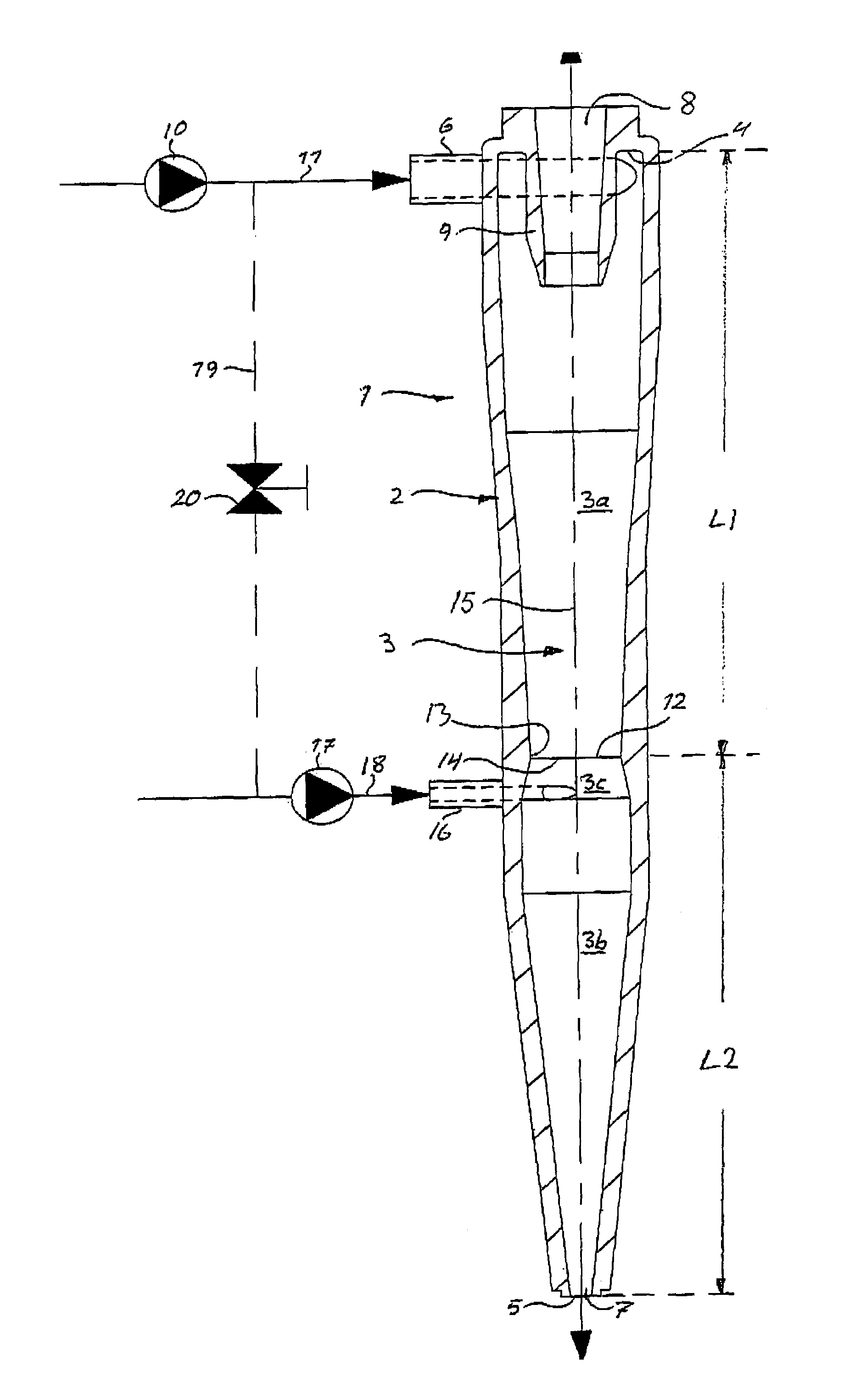
[0044]FIG. 1 shows a hydrocyclone unit 1 of the invention, which comprises a housing 2 that forms an elongate generally tapering separation chamber 3 with a base end 4 and an apex end 5. An inlet member 6 is provided on the housing 2 and designed to feed a fibre suspension to be separated tangentially into the separation chamber 3 at the base end 4 thereof. There are a reject fraction outlet 7 at the apex end 5 of the separation chamber 3 for discharging a created reject fraction of the suspension and a central accept fraction outlet 8, defined by a conventional vortex finder 9, at the base end 4 of the separation chamber 3 for discharging a created central fraction of the suspension.

[0045]In operation, a pump 10 pumps a fibre suspension containing heavy contaminants through a conduit 11 to the inlet member 6, which feeds the suspension tangent...


PUM

PropertyMeasurementUnit
sizeaaaaaaaaaa
diameteraaaaaaaaaa
length L2aaaaaaaaaa

Abstract

A hydrocyclone unit for separating a fibre pulp suspension containing relatively heavy contaminants has an elongate tapering separation chamber, an inlet member that feeds the suspension tangentially into the separation chamber at a base end, so as to form a vortex in the separation chamber, a reject fraction outlet at the apex end of the separation chamber for discharging a reject fraction containing heavy contaminants, and a central accept fraction outlet at the base end for discharging a central fraction containing fibres. A fluid injection member is adapted to inject a fluid tangentially into the separation chamber at a distance from the apex end which is at least 40% of the length of the separation chamber, such that the injected fluid increases the rotational speed of a portion of the vortex in the chamber to increase the separation efficiency with respect to fibres existing in the vortex portion.

Description

FIELD OF THE INVENTION[0001]The present invention relates to a hydrocyclone unit and method for separating a fibre pulp suspension containing relatively heavy contaminants.BACKGROUND OF THE INVENTION[0002]Hydrocyclones are used in the pulp and paper making industry for cleaning fibre pulp suspensions from contaminants, in particular but not exclusively from contaminants that differ from fibres in density. An important application is cleaning from contaminants in the form of heavy weight particles of a specific gravity greater than that of fibres, such as specks, shives, sand and metal particles in the size range of 100-1000 microns. The separation chamber of a conventional hydrocyclone designed for such an application normally has a diameter at the suspension inlet member smaller than about 150 mm to create centrifugal forces strong enough to pull the heavy contaminants radially outwardly in the vortex. The tapering design of the separation chamber is necessary to maintain the rotat...

Claims


Application Information

Patent Timeline
Patent Type & Authority Patents(United States)
IPC IPC(8): B04C5/13B04C7/00
CPCB04C5/081B04C5/14D21D5/24B04C5/26B04C5/18B04C2009/008
Inventor KUCHER, VALENTINABACKMAN, JAN
Owner GLV FINANCE HUNGARY KFT
Why Eureka
Try Eureka