Direct reduction process for the production of direct-reduced iron with high purity methane
a technology of methane and reduction process, which is applied in the direction of furnace components, furnace types, lighting and heating apparatus, etc., can solve the problems of plant difficulty in achieving full production capacity, and achieve the effect of reducing or substantially reducing the amount of non-reducing agents, reducing the content of reducing agents, and increasing the quantity of iron or
- Summary
- Abstract
- Description
- Claims
- Application Information
AI Technical Summary
Benefits of technology
Problems solved by technology
Method used
Image
Examples
example 1
Process to Produce DRI with Methane Enriched Reducing Stream-Membrane Separation of 15 mol. % N2
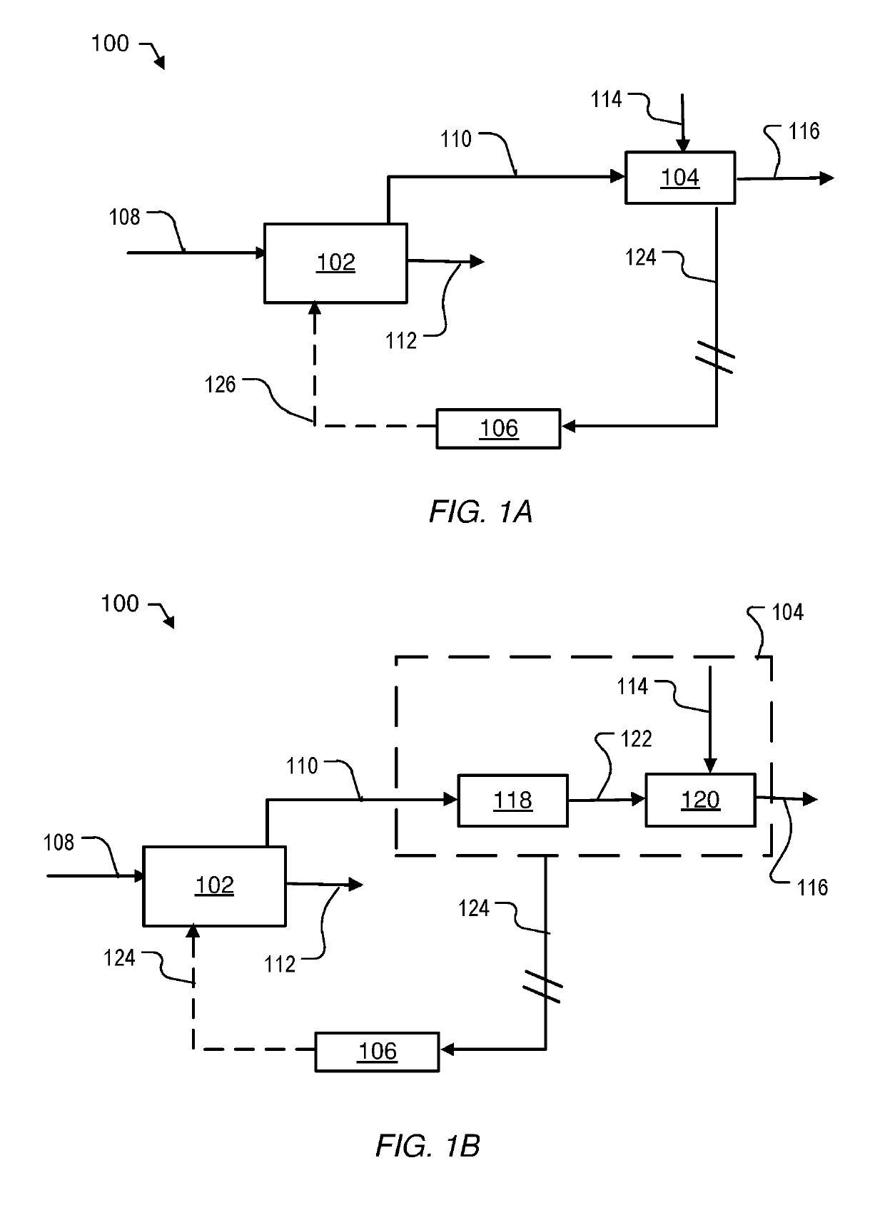
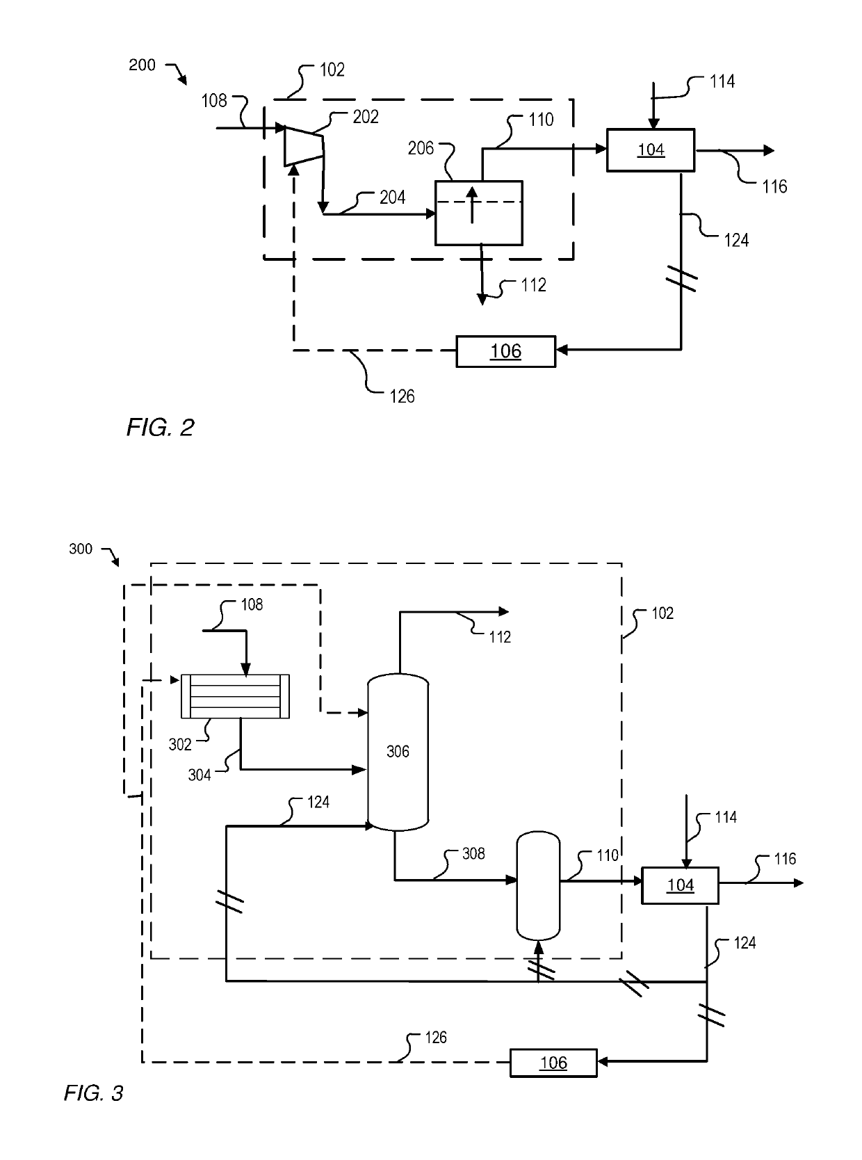
[0042]Un-treated natural gas (90° C., 7.9 bar, 300 kg / hr) with the mole fraction of each component given in Table 2 was fed into a membrane separation system. The untreated natural gas was first sent to a compressor where the pressure of the feed gas was increased to 35.5 bar. The high pressure gas was then sent to a methane permeable membrane to separate N2 rich gas (tail gas) from the untreated natural gas to obtain methane enriched reducing gas (237 kg / hr), which contained only 6 mol. % of N2 and 87 mol. % of methane. The reducing gas (237 kg / hr, 1750 cuft / hr) can be used to support 76.3 KTA iron steel production, while the same volume of un-treated natural gas can only support 70 KTA iron steel production. In other words, removing N2 from the natural gas can improve 9% capacity of the iron steel process. Note that the electricity required by running the compressor is about 26.7 kw, w...
example 2
Process to Produce DRI with Methane Enriched Reducing Stream-Membrane Separation of 10 mol. % N2
[0043]Un-treated natural gas (90° C., 7.9 bar, 274 kg / hr) with the mole fraction of each component given in Table 3 was fed into a membrane separation system. The untreated natural gas was first sent to a compressor where the pressure of the feed gas was increased to 35.5 bar. The high pressure gas was then sent to a methane permeable membrane to separate N2 rich gas (tail gas) from the untreated natural gas to obtain methane enriched reducing gas (218 kg / hr), which contained only 4 mol. % of N2 and 90 mol. % of methane. The reducing gas (218 kg / hr, 1650 cuft / hr) can be used to support 74.4 KTA iron steel production, while the same volume of un-treated natural gas can only support 70 KTA iron steel production. In other words, removing N2 from the natural gas can improve 9% capacity of the iron steel process. Note that the electricity required by running the compressor is about 25 kw, whi...
example 3
Process to Produce DRI with Methane Enriched Reducing Stream-Membrane Separation of 7 mol. % N2
[0044]Un-treated natural gas (90° C., 7.9 bar, 279 kg / hr) with the mole fraction of each component given in Table 4 was fed into a membrane separation system. The untreated natural gas was first sent to a compressor where the pressure of the feed gas was increased to 35.5 bar. The high pressure gas was then sent to a methane permeable membrane to separate N2 rich gas (tail gas) from the untreated natural gas to obtain methane enriched reducing gas (212 kg / hr), which contained only 2 mol. % of N2 and 90 mol. % of methane. The reducing gas (212 kg / hr, 1588 cuft / hr) can be used to support 71.7 KTA iron steel production, while the same volume of un-treated natural gas can only support 70 KTA iron steel production. In other words, removing N2 from the natural gas can improve 2.4% capacity of the iron steel process. Note that the electricity required by running the compressor is about 27.5 kw, ...
PUM
| Property | Measurement | Unit |
|---|---|---|
| melting point | aaaaa | aaaaa |
| wt. % | aaaaa | aaaaa |
| capturing energy | aaaaa | aaaaa |
Abstract
Description
Claims
Application Information
 - R&D
- Intellectual Property
- Life Sciences
- Materials
- Tech Scout
- Unparalleled Data Quality
- Higher Quality Content
- 60% Fewer Hallucinations
Browse by: Latest US Patents, China's latest patents, Technical Efficacy Thesaurus, Application Domain, Technology Topic, Popular Technical Reports.
© 2025 PatSnap. All rights reserved.Legal|Privacy policy|Modern Slavery Act Transparency Statement|Sitemap|About US| Contact US: help@patsnap.com


