Equipment and method for electrolytic recovery of metal

a technology of electrolytic recovery and equipment, which is applied in the field of gas duct system and equipment and a metal electrolytic recovery method, can solve the problems of not increasing indefinitely and achieve the effect of increasing the current density without lowering the quality of the precipitate, reducing pressure, and increasing the production capacity of plants

Active Publication Date: 2014-08-21
OUTOTEC OYJ
View PDF2 Cites 0 Cited by
  • Summary
  • Abstract
  • Description
  • Claims
  • Application Information

AI Technical Summary

Benefits of technology

[0008]With the solution according to the invention it is possible to use a higher current density without lowering the quality of the metal precipitate. The production capacity of plants can thus be increased. The gas bubbles promoting process conditions in the basin can be kept small enough, which promotes an optimum mixing event on the cathode surface. With the aid of the invention an even wall of bubbles of a small size can be achieved using a lower pressure and with an even lower energy consumption than before.

Problems solved by technology

The precipitation rate of the metal, such as copper, depends on the current density, but this can not be increased indefinitely without lowering the quality of the precipitate.

Method used


Image

  • Equipment and method for electrolytic recovery of metal
  • Equipment and method for electrolytic recovery of metal
  • Equipment and method for electrolytic recovery of metal

Examples


example 1

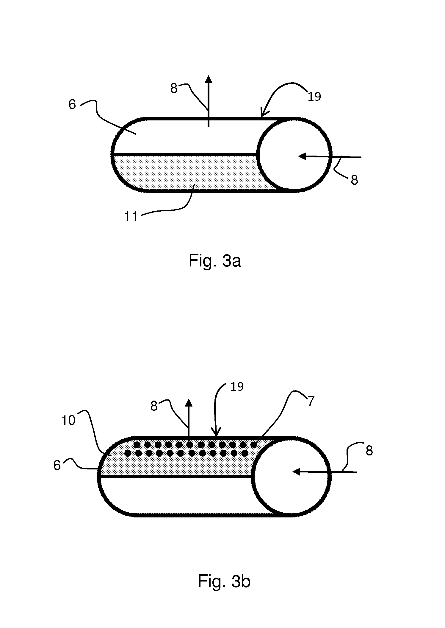
[0021]About 10 m of seepage hose was placed in a framework forming nine rows, each row one metre long. The hose was treated with suitable glue, so that the air to be blown through the pipe was not allowed to penetrate from the pipe walls other than directly upwards. The framework was placed in a transparent cell, which was filled with water. When blowing air into the seepage hose piping at a rate of 120 ml m−1 min−1 from the hoses, an even bubble wall resulted with the bubble size varying within a range of 0.1-3 mm.

example 2

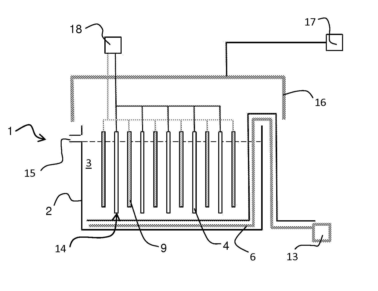
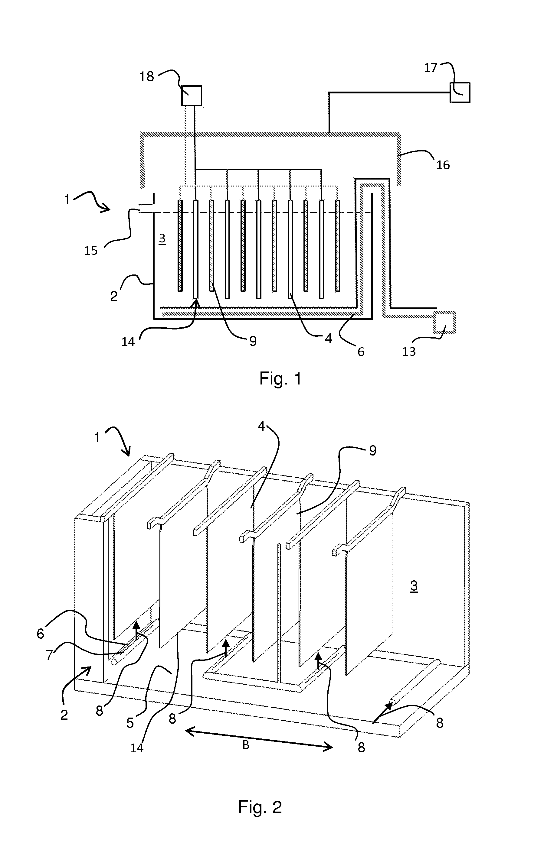
[0022]An industrial fabric was wrapped tightly around a metal pipe having holes pointing directly upwards. The pipe was placed on the bottom of an electrolysis cell having a height of 1.2 m (width 25 cm, volume 62 L) under a steel plate functioning as a cathode, so that when blowing air into the piping, bubbles were distributed from the bottom edge of the cathode and they ascended uniformly to both sides of the cathode. The cell was filled with an electrolyte containing 40 g / l of copper and 175 g / l of sulphuric acid. 46.5 L / h of electrolyte was supplied into the cell and the temperature of the electrolyte was 45° C. during the test. Copper was precipitated on to the cathode surface for 24 h using a current density of 450 Am −2, at the same time blowing air through the piping. The surface of the copper precipitate formed was examined with a SEM microscope (scanning electron microscope) and with an optical microscope. In addition, a cross-sectional micro-section was examined with an o...

example 3

[0023]With the equipment of Example 2, a bubbling piping was placed in a transverse position against the cathodes. Guiding components were attached to the anodes to guide the bubbles uniformly on to the cathode surface. The test according to Example 2 was repeated using a current density of 450 Am−2 and the copper precipitate was examined. The precipitate had a smooth surface, it was dense and the crystalline growth was uniform, as in the case of Example 2, where the copper precipitate was produced with the aid of bubbling.


PUM

PropertyMeasurementUnit
diameteraaaaaaaaaa
diameteraaaaaaaaaa
distanceaaaaaaaaaa

Abstract

The invention concerns a system of gas ducts (6) for transporting gas, for example, into electrolytic equipment, in connection with which there are means (13) for taking at least gas into the system of gas ducts, whereby there is a suitable number of gas supply holes (7) in the system of gas ducts in a wall (19) limiting the system of gas ducts, whereby the material, such as gas, flowing in the system of gas ducts (6) is prevented at least in part from passing through the wall (19) of the system of gas ducts (6). The invention also concerns equipment and a method for electrolytic recovery of metal, such as copper.

Description

FIELD OF THE INVENTION[0001]The invention concerns a gas duct system as well as equipment and a method for electrolytic recovery of metal, such as copper, as defined in the independent claims.BACKGROUND OF THE INVENTION[0002]Electrolytic recovery, for example, is used as a hydro-metallurgic method when production of pure metal, such as copper, is the objective. In the recovery electrolysis, copper is reduced directly from the electrolytic solution, which is a copper sulphate solution. In the process, copper is precipitated on to the surface of cathodes made of, for example, acid-proof steel, whereupon the copper is removed mechanically from the plate surface. The anodes are insoluble metal plates in the process. The precipitation rate of the metal, such as copper, depends on the current density, but this can not be increased indefinitely without lowering the quality of the precipitate. In practice, the highest possible current density is determined by the so-called critical maximum ...

Claims


Application Information

Patent Timeline
Patent Type & Authority Applications(United States)
IPC IPC(8): C25C7/06C25C1/12
CPCC25C1/12C25C7/06
Inventor NIEMINEN, VILLEPALMU, LAURIVIRTANEN, HENRI
Owner OUTOTEC OYJ
Why Eureka
Try Eureka