Method for installing refrigeration device, and refrigeration device

a technology for installing refrigeration devices and refrigeration devices, which is applied in the direction of refrigeration machines, compression machines with reversible cycles, lighting and heating apparatus, etc. it can solve the problems of increasing the operating pressure due to non-condensable gases, atmospheric components, and the degradation of refrigerant, so as to reduce the number of separate components and simplify the structure of the device

Inactive Publication Date: 2008-04-15
DAIKIN IND LTD
View PDF20 Cites 12 Cited by
  • Summary
  • Abstract
  • Description
  • Claims
  • Application Information

AI Technical Summary

Benefits of technology

[0012]In order to obviate the evacuation operation, an object of the present invention is to enhance the separation efficiency of non-condensable gas in the separation membrane in a refrigeration device provided with a constitution capable of separating and removing non-condensable gas remaining inside the refrigerant connection pipe in a state of mixture with the refrigerant in the refrigeration circuit at the time of on-site installation.

Problems solved by technology

Installation of the type of air conditioning device described above has drawbacks in that the process of evacuating the refrigerant connection pipe necessitates the complex operations of connecting a vacuum pump to the liquid refrigerant connection pipe and the gas refrigerant connection pipe, and performing other operations that are important for preventing release of refrigerant into the atmosphere; degradation of the refrigerant and refrigerator oil due to residual oxygen gas; an increase in operating pressure due to non-condensable gases primarily composed of oxygen gas, nitrogen gas, and other atmospheric components; and other effects.
However, since a large quantity of the adsorbent agent must be used in order to adsorb all of the non-condensable gas included in the refrigerant in this air conditioning device, the device as a whole is enlarged, and is difficult to actually mount in a refrigeration device.
However, this air conditioning device has drawbacks in that the separation efficiency of the non-condensable gas in the separation membrane is low because it is impossible to increase the pressure difference between the primary side (specifically, the inside of the refrigerant circuit) of the separation membrane and the secondary side (specifically, the outside of the refrigerant circuit).

Method used


Image

  • Method for installing refrigeration device, and refrigeration device
  • Method for installing refrigeration device, and refrigeration device
  • Method for installing refrigeration device, and refrigeration device

Examples


first embodiment

1 Structure of the Air Conditioning Device

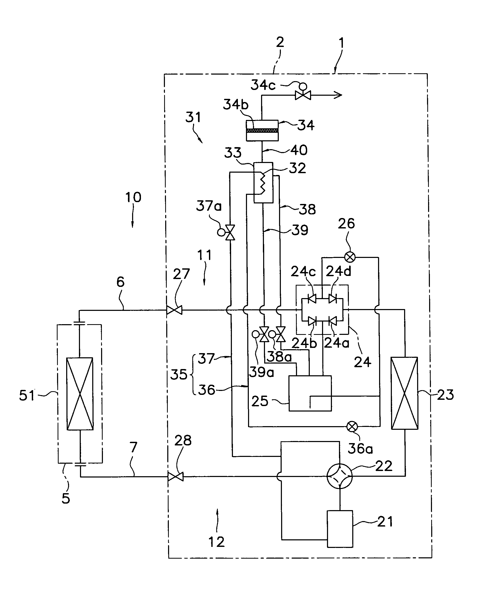
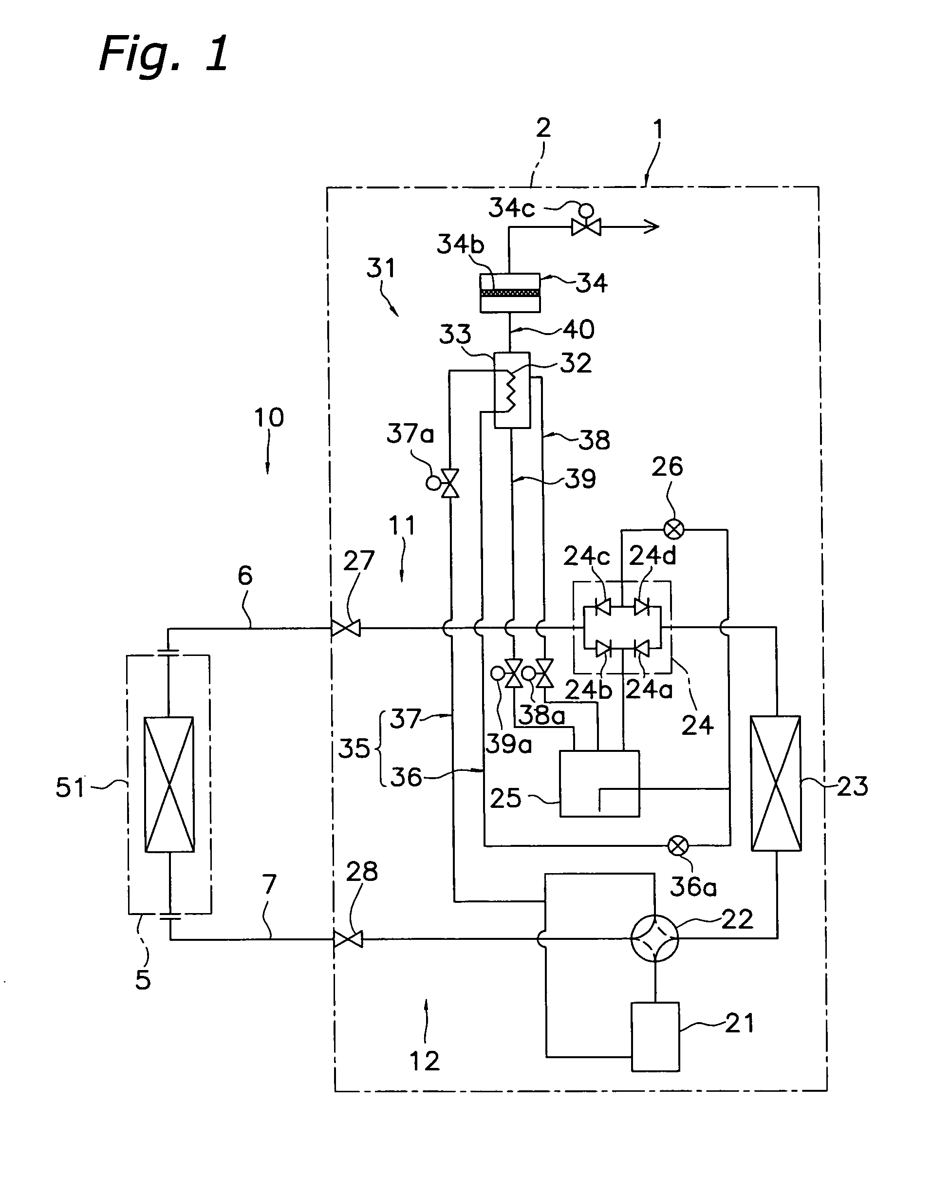
[0066]FIG. 1 is a schematic diagram of a refrigerant circuit of an air conditioning device 1 as an example of a refrigeration device according to a first embodiment of the present invention. The air conditioning device 1 in the present embodiment is an air conditioning device capable of cooling operation and heating operation, and is provided with a heat source unit 2, a utilization unit 5, and a liquid refrigerant connection pipe 6 and gas refrigerant connection pipe 7 for connecting the heat source unit 2 with the utilization unit 5.

[0067]The utilization unit 5 mainly comprises a utilization-side heat exchanger 51.

[0068]The utilization-side heat exchanger 51 is a heat exchanger that is capable of cooling or heating the air inside a room by evaporating or condensing the refrigerant that flows therethrough.

[0069]The heat source unit 2 mainly comprises a compressor 21, a four-way directional valve 22, a heat-source-side heat exchanger 23, a b...

modification 4

7 Modification 4

[0117]In the abovementioned gas separation devices 31, 131, 231, and 331, the liquid refrigerant outflow circuit 39 for discharging to the outside of the secondary receiver 33 the liquid refrigerant condensed by the cooler 32 and collected in the bottom of the secondary receiver 33 is connected so as to return the liquid refrigerant to the main receiver 25. However, a liquid refrigerant outflow circuit 439 may also be provided so as to form a connection between the secondary receiver 33 and the downstream side of the heat-source side expansion valve 26 (specifically, between the downstream side of the heat-source side expansion valve 26 and the non-return valves 24c and 24d of the bridge circuit 24), as in the gas separation device 431 incorporated into the heat source unit 402 of the air conditioning device 401 of the present modification shown in FIG. 6.

modification 5

8 Modification 5

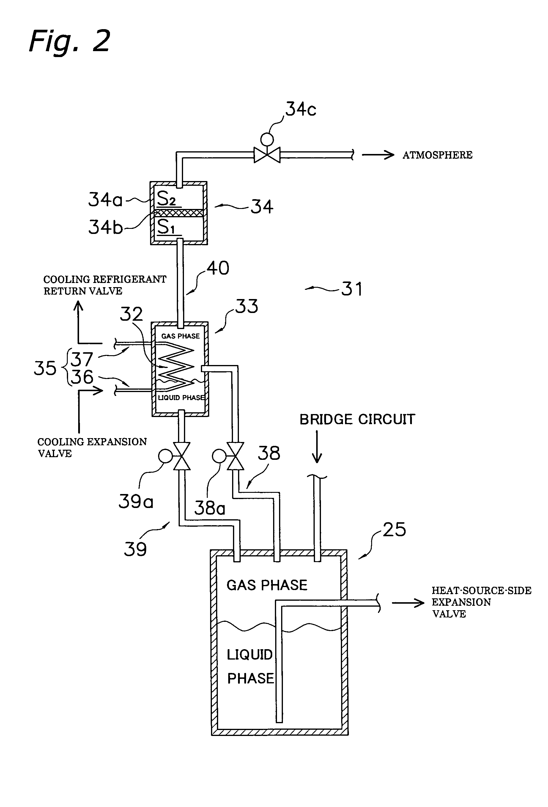
[0118]In the abovementioned gas separation devices 31, 131, 231, and 431, the secondary receiver 33 having the cooler 32 disposed in the interior thereof is connected to the separation membrane device 34 via the separation membrane introduction circuit 40. However, the separation membrane device 34 may also be integrally formed with the secondary receiver 33 having the cooler 32 disposed in the interior thereof, as in the gas separation device 531 incorporated into the heat source unit 502 of the air conditioning device 501 of the present modification shown in FIG. 7. The number of separate components constituting the gas separation device 531 is thereby reduced, and the structure of the device is simplified.


PUM


Abstract

An air conditioning device has a heat source unit and a utilization unit connected via a refrigerant connection pipe to form a refrigerant circuit, and has a cooler, a secondary receiver, and a separation membrane device. The cooler cools at least a portion of the refrigerant that flows through the liquid-side refrigerant circuit as the compressor is operated and the refrigerant in the refrigerant circuit is recirculated. The secondary receiver separates the refrigerant cooled by the cooler into a liquid refrigerant and a gas refrigerant that includes non-condensable gas. The separation membrane device has a separation membrane for separating the non-condensable gas from the gas refrigerant obtained by gas-liquid separation, and discharges the non-condensable gas thus separated to the outside of the refrigerant circuit.

Description

CROSS-REFERENCE TO RELATED APPLICATIONS[0001]This U.S. National Stage application claims priority under 35 U.S.C. §119(a) to Japanese Patent Application No. 2003-361827 filed in Japan on Oct. 22, 2003, the entire contents of which are hereby incorporated herein by reference.TECHNICAL FIELD[0002]The present invention relates to a method for installing a refrigeration device and to a refrigeration device. The present invention particularly relates to a refrigeration device provided with a heat source unit having a compressor and a heat-source-side heat exchanger, a utilization unit having a utilization-side heat exchanger, and a refrigerant connection pipe for connecting the heat source unit and the utilization unit; and to a method for installing the same.BACKGROUND ART[0003]A separation-type air conditioning device is one type of conventional refrigeration device. This type of air conditioning device is mainly provided with a heat source unit having a compressor and a heat-source-si...

Claims


Application Information

Patent Timeline
Patent Type & Authority Patents(United States)
IPC IPC(8): F25B43/04F25B13/00F25B43/00F25B45/00
CPCF25B13/00F25B43/043F25B2313/0272F25B43/04F25B1/00
Inventor YOSHIMI, MANABUMATSUI, NOBUKIMATSUOKA, HIROMUMEMIZUTANI, KAZUHIDE
Owner DAIKIN IND LTD
Why Eureka
Try Eureka