Method for installing refrigeration device, and refrigeration device

Inactive Publication Date: 2007-05-24
DAIKIN IND LTD
View PDF3 Cites 17 Cited by
  • Summary
  • Abstract
  • Description
  • Claims
  • Application Information

AI Technical Summary

Benefits of technology

[0037] The separation membrane device is integrally formed with the gas-liquid separator in this refrigeration

Problems solved by technology

Installation of the type of air conditioning device described above has drawbacks in that the process of evacuating the refrigerant connection pipe necessitates the complex operations of connecting a vacuum pump to the liquid refrigerant connection pipe and the gas refrigerant connection pipe, and performing other operations that are important for preventing release of refrigerant into the atmosphere; degradation of the refrigerant and refrigerator oil due to residual oxygen gas; an increase in operating pressure due to non-condensable gases primarily composed of oxygen gas, nitrogen gas, and other atmospheric components; and other effects.
However,

Method used


Image

  • Method for installing refrigeration device, and refrigeration device
  • Method for installing refrigeration device, and refrigeration device
  • Method for installing refrigeration device, and refrigeration device

Examples


Example

First Embodiment

Structure of the Air Conditioning Device

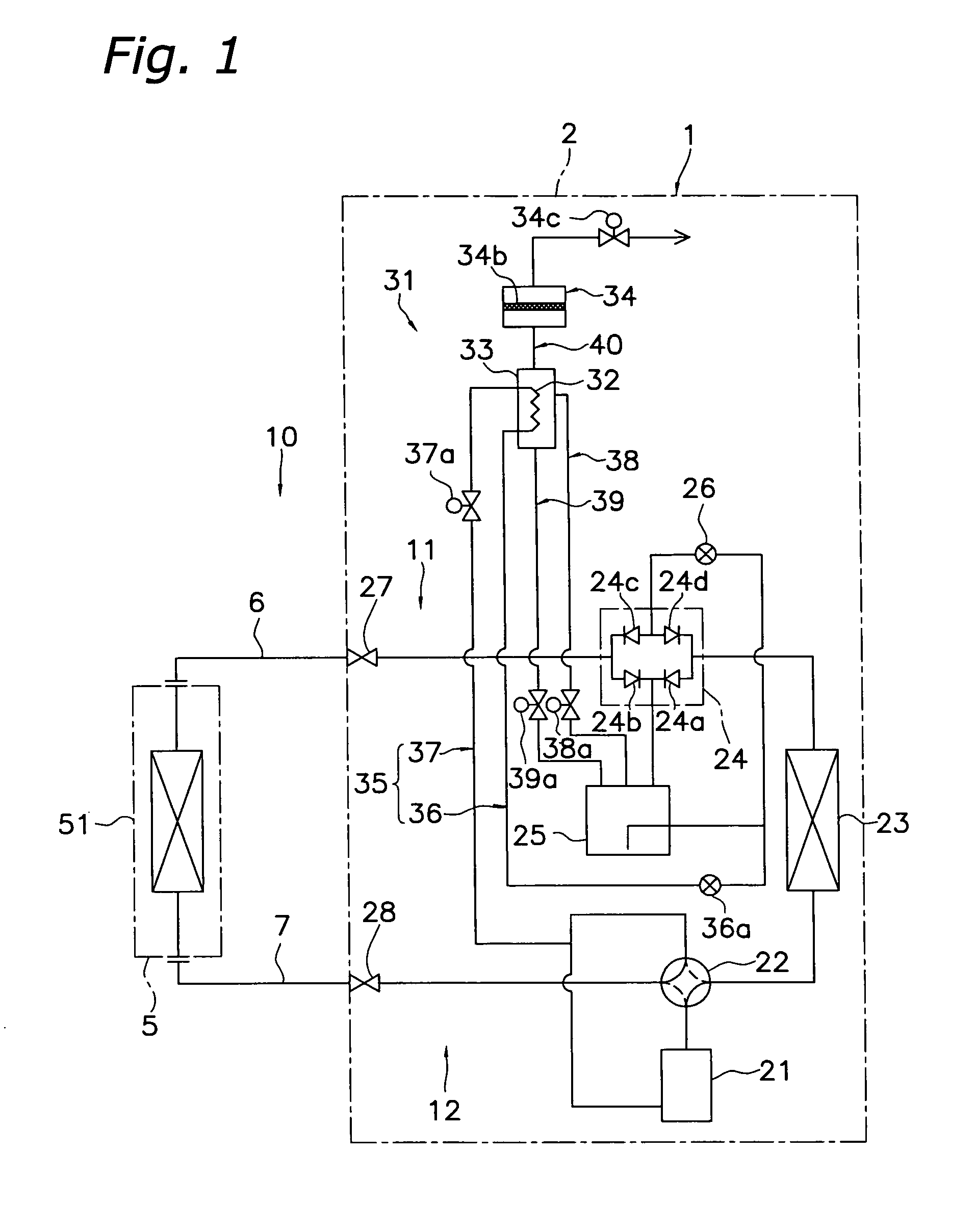
[0084]FIG. 1 is a schematic diagram of a refrigerant circuit of an air conditioning device 1 as an example of a refrigeration device according to a first embodiment of the present invention. The air conditioning device 1 in the present embodiment is an air conditioning device capable of cooling operation and heating operation, and is provided with a heat source unit 2, a utilization unit 5, and a liquid refrigerant connection pipe 6 and gas refrigerant connection pipe 7 for connecting the heat source unit 2 with the utilization unit 5.

[0085] The utilization unit 5 mainly comprises a utilization-side heat exchanger 51.

[0086] The utilization-side heat exchanger 51 is a heat exchanger that is capable of cooling or heating the air inside a room by evaporating or condensing the refrigerant that flows therethrough.

[0087] The heat source unit 2 mainly comprises a compressor 21, a four-way directional valve 22, a heat-source-side...

Example

Second Embodiment

Structure of the Air Conditioning Device

[0142]FIG. 11 is a schematic diagram of the refrigerant circuit of the air conditioning device 1001 as an example of the refrigeration device according to a second embodiment of the present invention. The air conditioning device 1001 in the present embodiment is an air conditioning device capable of cooling operation and heating operation, the same as the air conditioning device 1 of the first embodiment, and is provided with a heat source unit 1002, a utilization unit 5, and a liquid refrigerant connection pipe 6 and gas refrigerant connection pipe 7 for connecting the heat source unit 1002 with the utilization unit 1005. Since the structure of the air conditioning device 1001 of the present embodiment except for the gas separation device 1031 is the same as that of the air conditioning device 1 of the first embodiment, description thereof is omitted.

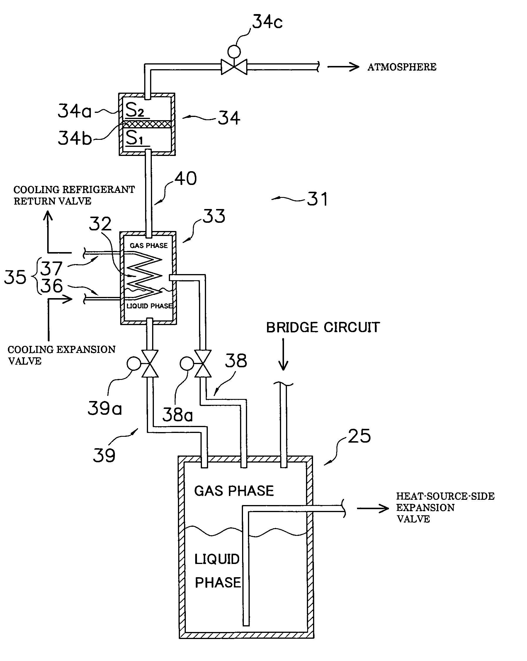
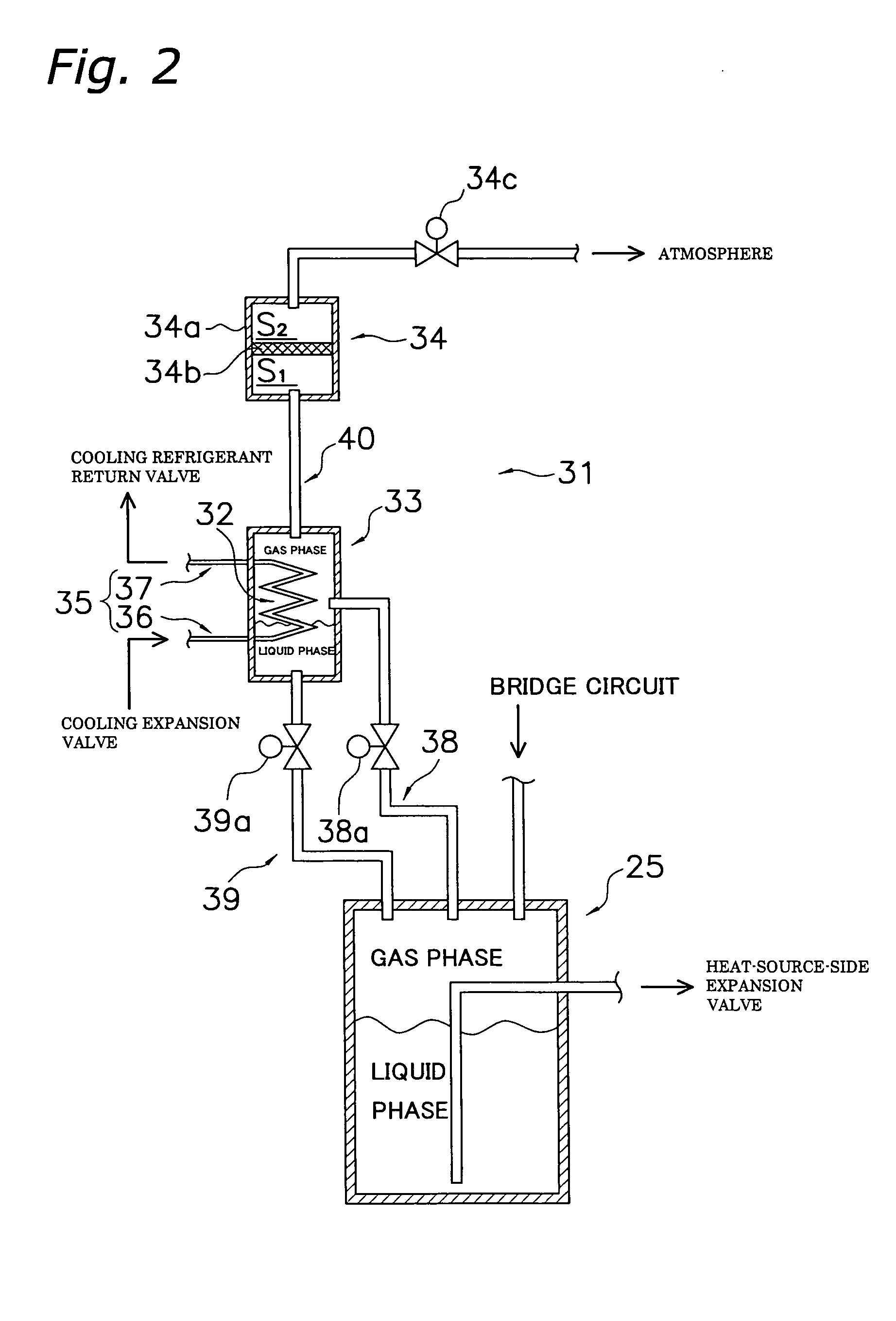
[0143] The gas separation device 1031 in the present embodiment is prima...

Example

Third Embodiment

Structure and Features of the Air Conditioning Device

[0159]FIG. 14 is a schematic diagram of the refrigerant circuit of the air conditioning device 1501 as an example of the refrigeration device according to a third embodiment of the present invention. The air conditioning device 1501 in the present embodiment is an air conditioning device capable of cooling operation and heating operation, the same as the air conditioning device 1 of the first embodiment, and is provided with a heat source unit 1502, a utilization unit 5, and a liquid refrigerant connection pipe 6 and gas refrigerant connection pipe 7 for connecting the heat source unit 1502 and the utilization unit 5. Since the structure of the air conditioning device 1501 of the present embodiment except for the gas separation device 1531 is the same as that of the air conditioning device 1 of the first embodiment, description thereof is omitted.

[0160] The gas separation device 1531 in the present embodiment i...


PUM


Abstract

The separation efficiency of non-condensable gas in the separation membrane is enhanced in a refrigeration device provided with a configuration whereby non-condensable gas remaining in the refrigerant connection pipes at the time of on-site installation can be separated and removed from a state of mixture with the refrigerant in the refrigerant circuit using a separation membrane. An air conditioning device 1 comprises a heat source unit (2) and a utilization unit (5) connected via a refrigerant connection pipe (6, 7) to form a refrigerant circuit (10), and has a cooler (32), a secondary receiver (33), and a separation membrane device (34). The cooler (32) cools at least a portion of the refrigerant that flows through the liquid-side refrigerant circuit (11) as the compressor (21) is operated and the refrigerant in the refrigerant circuit (10) is recirculated. The secondary receiver (33) separates the refrigerant cooled by the cooler (32) into a liquid refrigerant and a gas refrigerant that includes non-condensable gas. The separation membrane device (34) has a separation membrane (34b) for separating the non-condensable gas from the gas refrigerant obtained by gas-liquid separation, and discharges the non-condensable gas thus separated to the outside of the refrigerant circuit (10).

Description

TECHNICAL FIELD [0001] The present invention relates to a method for installing a refrigeration device and to a refrigeration device. The present invention particularly relates to a refrigeration device provided with a heat source unit having a compressor and a heat-source-side heat exchanger, a utilization unit having a utilization-side heat exchanger, and a refrigerant connection pipe for connecting the heat source unit and the utilization unit; and to a method for installing the same. BACKGROUND ART [0002] A separation-type air conditioning device is one type of conventional refrigeration device. This type of air conditioning device is mainly provided with a heat source unit having a compressor and a heat-source-side heat exchanger, a utilization unit having a utilization-side heat exchanger, and a liquid refrigerant connection pipe and gas refrigerant connection pipe for connecting the units to each other. [0003] In this type of air conditioning device, the sequence of implement...

Claims


Application Information

Patent Timeline
IPC IPC(8): F25B43/04F25B43/00F25B13/00F25B45/00
CPCF25B13/00F25B43/043F25B2313/0272F25B1/00F25B43/04
Inventor YOSHIMI, MANABUMATSUI, NOBUKIMATSUOKA, HIROMUNEMIZUTANI, KAZUHIDE
Owner DAIKIN IND LTD
Why Eureka
Try Eureka