

Chip card holder with protective cover for portable electronic devices
a technology of electronic devices and chip cards, applied in the direction of incorrect coupling prevention, coupling device connection, instruments, etc., can solve the problems of dust or water entering the clearance between the exposed portion and affecting the appearan
- Summary
- Abstract
- Description
- Claims
- Application Information
AI Technical Summary
Benefits of technology
Problems solved by technology
Method used
Image

Examples
Embodiment Construction
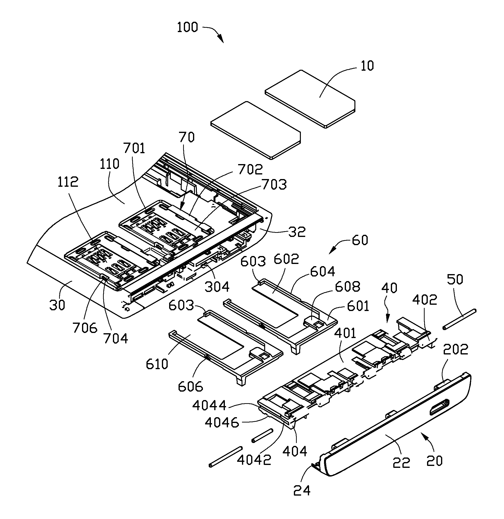
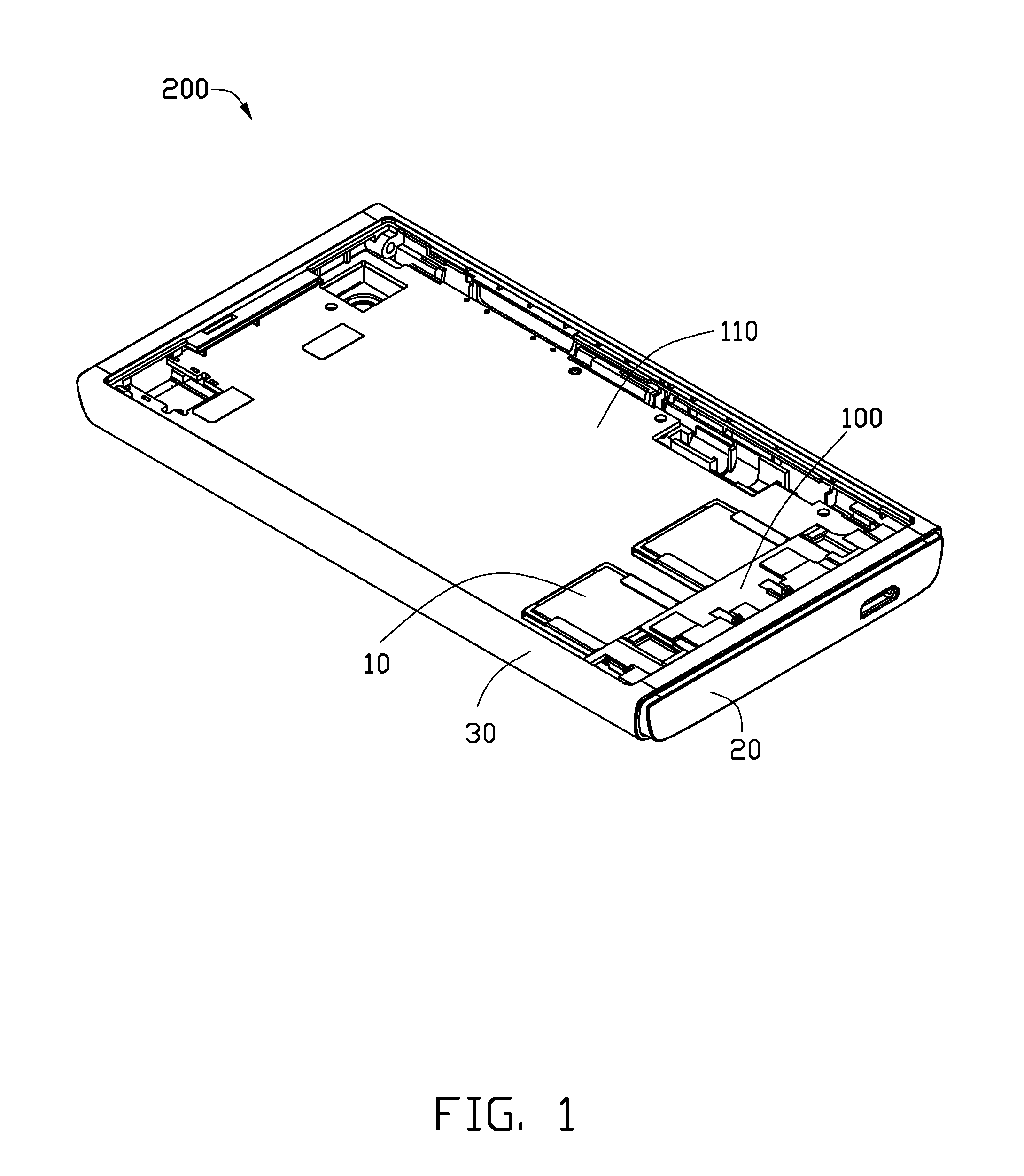
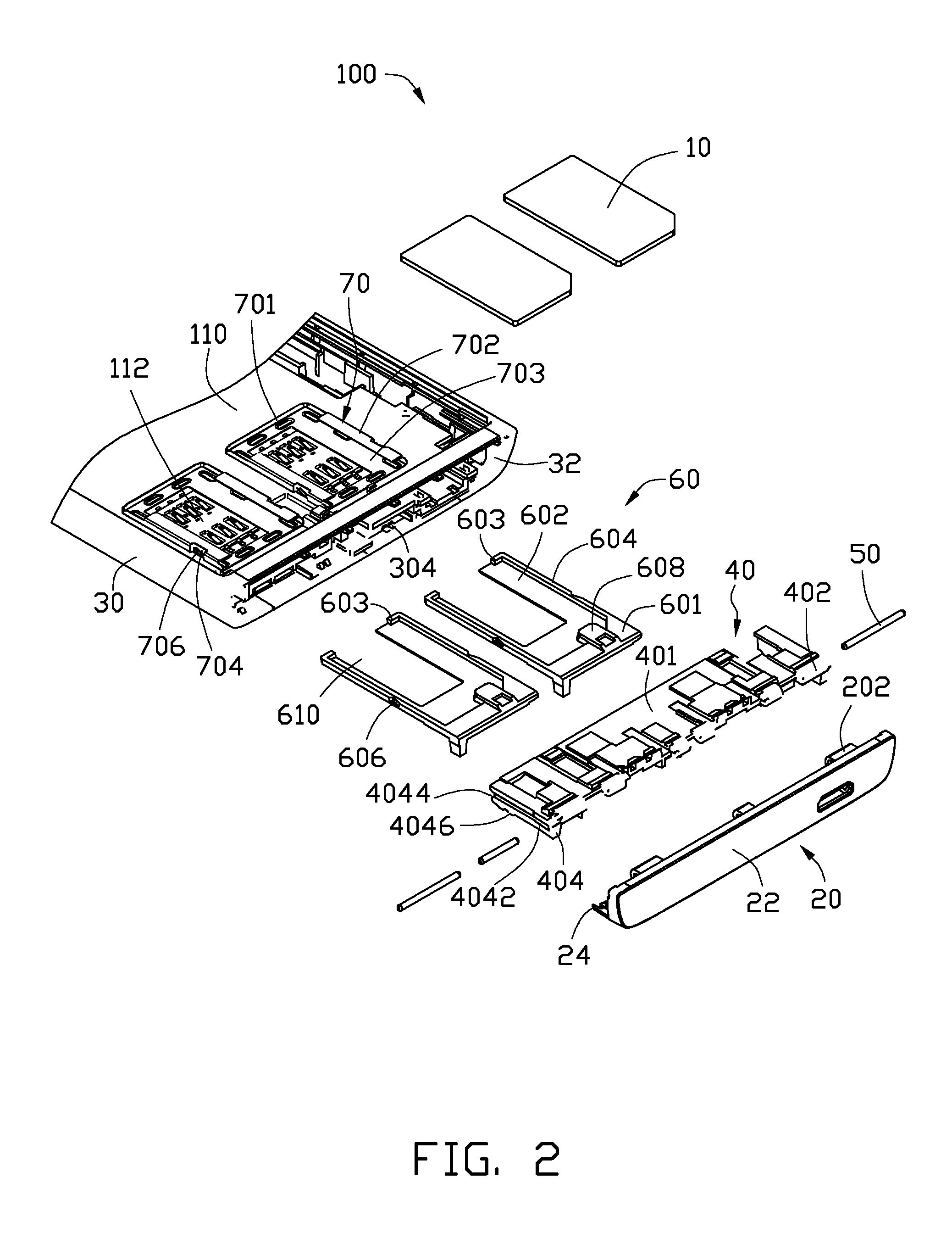
[0015]Referring to FIGS. 1 to 3, shown is an exemplary embodiment of a chip card holder which can be used on a portable electronic device 200, such as a cellular phone or any electronic device where a chip card is required. The portable electronic device 200 comprises a housing 30, a chip card holder 100, two chip cards 10, and a printed circuit board (PCB) 110. The chip card holder 100 is assembled to the housing 30. The chip cards 10 can be selectively placed in the chip card holder 100. The chip cards 10 may be subscriber identity module (SIM) cards or flash cards; or one of each. The PCB 110 is fixed to the housing 30.
[0016]The chip card holder 100 comprises a protective cover 20, a seat 40, at least one pivotable shaft 50, two trays 60, and two receiving frames 70.
[0017]The housing 30 may be a portion of the portable electronic device 200 or a separate element fixed to the portable electronic device 200. In this exemplary embodiment, the housing 30 is a top portion or a bottom ...
PUM
 Abstract
Description
Claims
Application Information