Tracheostomy appliances and methods for the treatment of sleep apnea syndromes

a tracheostomy and sleep apnea technology, applied in the field of tracheostomy appliances and methods for the treatment of sleep apnea syndrome, can solve the problems of insufficient trans-thoracic pressure gradient, insufficient measurement reliability, and inability to overcome rising airway resistance, so as to prevent an undersirable increase in co2 level and minimal adverse effect on patient appearan

Inactive Publication Date: 2014-08-12
SCOTT ELAINE D
View PDF30 Cites 4 Cited by
  • Summary
  • Abstract
  • Description
  • Claims
  • Application Information

AI Technical Summary

Benefits of technology

[0021]More specifically, in one embodiment of the present invention, useful in treating apneic patients in health, a small caliber catheter is emplaced surgically trans-tracheally for equalizing intra-tracheal pressure relative to ambient pressure under certain conditions of inspiration by permitting very limited air inflow. This miniature version functions to prevent an undersirable increase in CO2 level which would otherwise cause arousal from sleep. It presents a minimal adverse affect on patient appearance.

Problems solved by technology

Some humans are believed to collapse part of their upper airway as they inspire during sleep causing increased resistance to airflow resulting in disruption of physiologic sleep.
Measurements of airflow and respiratory effort are central to the understanding of respiratory dynamics of sleep, yet these measurements are the least reliable of those available.
There is a theoretical point at which the trans-thoracic pressure gradient will be insufficient to overcome rising airway resistance.
When the CO2 level exceeds 40 mmHg, inspiration begins again, and this generally causes disturbance of sleep.
Even though respiratory effort is seen and measured in OSA, minute ventilation is presumed to be inadequate (hypoventilation) to maintain normal levels of carbon dioxide in the blood.
With slower flux of bicarbonate in the cerebrospinal fluid, corrections in carbon dioxide levels will be slower and synchrony of blood chemistry and breathing dynamics will be impaired.
Because of the poor technical quality of airflow and respiratory effort measurements, ‘apnea’ and ‘hypopnea’ are largely subjective terms.
Tracheostomy appliances were designed to replace the use of endotracheal tubes inserted through the nose or mouth of the patient since long-term use of endotracheal tubes can cause unacceptable trauma to the airway and prevents the patient from eating and talking.

Method used


Image

  • Tracheostomy appliances and methods for the treatment of sleep apnea syndromes
  • Tracheostomy appliances and methods for the treatment of sleep apnea syndromes
  • Tracheostomy appliances and methods for the treatment of sleep apnea syndromes

Examples


Embodiment Construction

[0036]With the Background of the Invention in mind, and incorporated by reference herein, and with reference to the Drawings, the miniature embodiment of FIGS. 1-3, is described in conjunction with a method of treating an adult patient in health for sleep apnea.

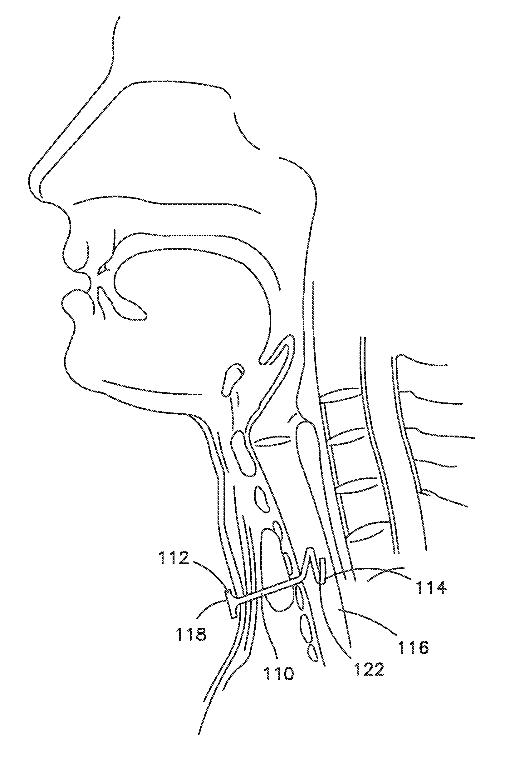
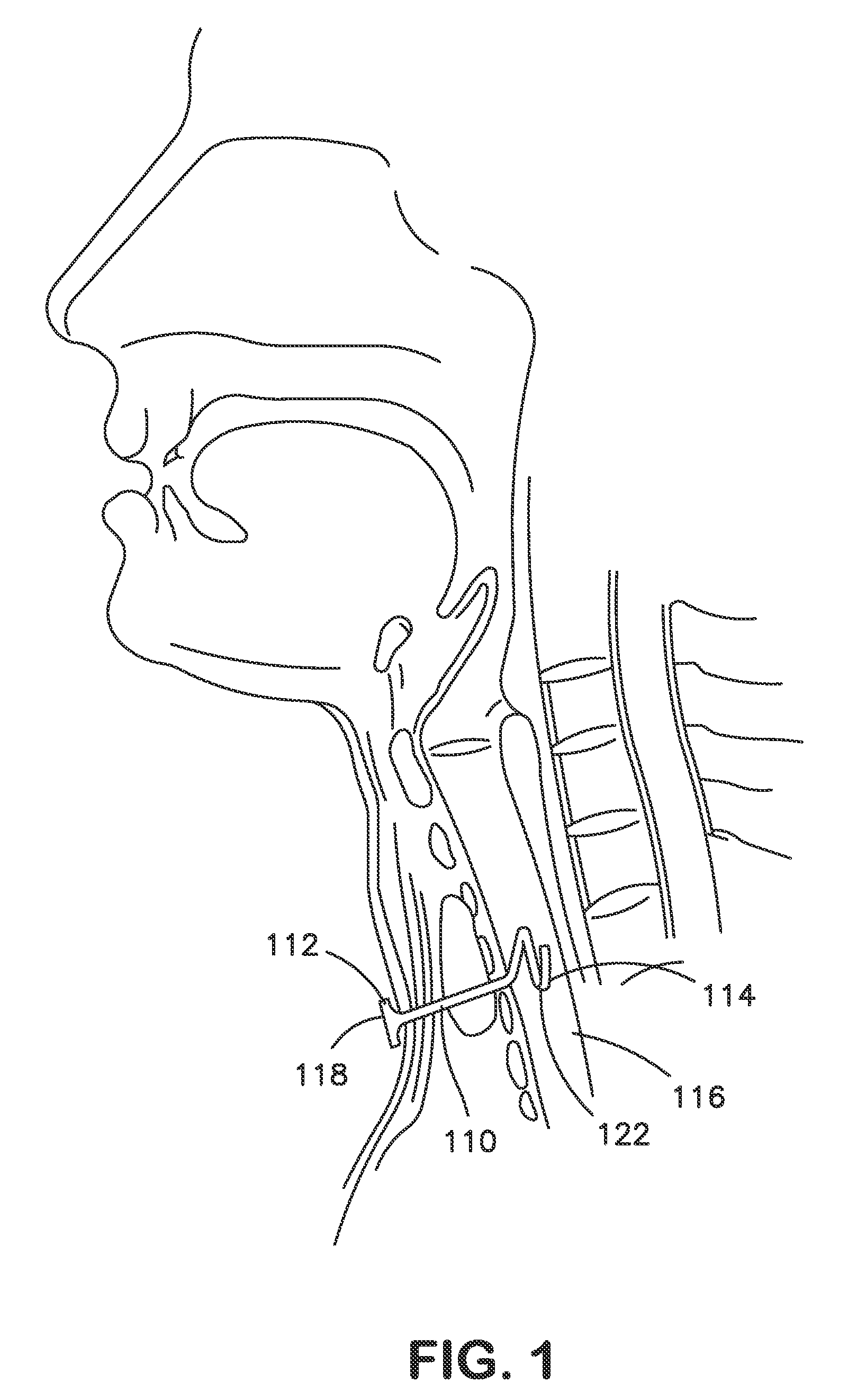
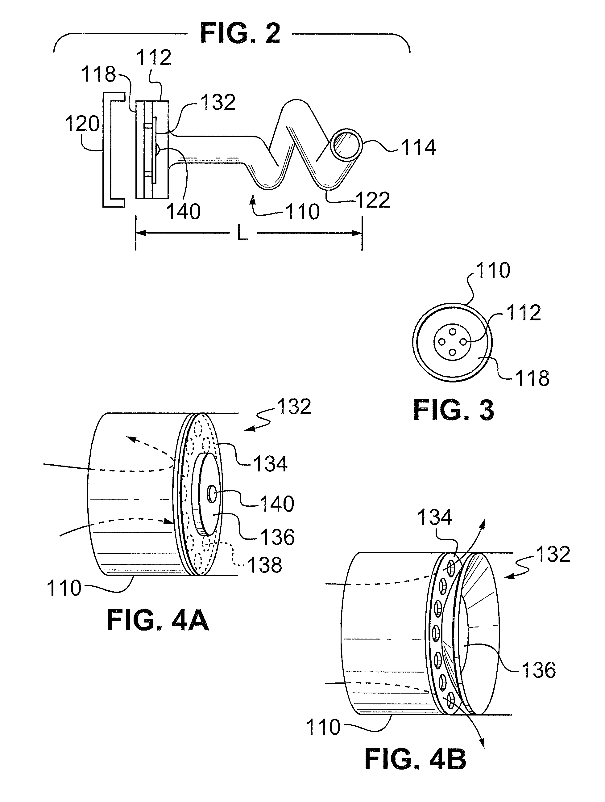
[0037]Referring to FIG. 1, the method comprises the step of implanting in a tracheotomy, an appliance, such as a catheter 110, having a vent 112 with at least one distal port 114 communicating with the interior of the patient's trachea 116 and a proximal port 118. (As used herein, proximal is nearer to the implanting surgeon, and distal further from the implanting surgeon.) The distal port 114 is for the purpose of sensing intra-tracheal pressure, and the proximal port 118 is for sensing ambient atmospheric air pressure which, at sea level under standard conditions is 1000 mm Hg. In the illustrated embodiment, the vent 112 provides a small continuous flow path between the proximal and distal ports, 118 and 114.

[0038]A removab...


PUM


Abstract

Small tracheostomy appliances for use in treating Sleep Apnea Syndrome. The appliances are inserted in a tracheotomy incision, low on a patient's neck to equalize intra-tracheal pressure with ambient pressure under certain conditions to prevent undesirable increases in blood CO2 that could otherwise cause arousals from sleep.

Description

CROSS-REFERENCE TO RELATED APPLICATIONS[0001]This application is a continuation-in-part of U.S. patent application Ser. No. 11 / 368,993 filed on Mar. 6, 2006 which claims the benefit under 35 USC §119(e) of U.S. Provisional Patent Application No. 60 / 659,771, filed Mar. 9, 2005.BACKGROUND OF THE INVENTION[0002]Some humans are believed to collapse part of their upper airway as they inspire during sleep causing increased resistance to airflow resulting in disruption of physiologic sleep.[0003]Obstructive Sleep Apnea (OSA) is the term applied to this phenomenon, and it is diagnosed using electroencephalography (EEG), electro-oculography (EOG), electromyography (EMG), electrocardiography (ECG), and pulse oximetry (POX)—all well-established diagnostic tools. Breathing effort is measured as expansion of the chest and abdomen by recording the stretch of belts fitted to subjects during the study. Airflow is measured at the nose and mouth by a variety of sensors. Measurements of airflow and re...

Claims


Application Information

Patent Timeline
Patent Type & Authority Patents(United States)
IPC IPC(8): A61M11/00
CPCA61M2230/40A61M2205/04A61M16/0003A61B17/3468A61M2210/1032A61M2016/0027A61M2230/005A61M16/0468A61F5/56A61M16/0472A61M2205/3303
Inventor SCOTT, S., DAVID
Owner SCOTT ELAINE D
Why Eureka
Try Eureka