Machining apparatus

a technology of machining apparatus and machine, which is applied in the direction of ventilation systems, heating types, stoves or ranges, etc., can solve the problems of affecting the appearance of the machine apparatus, the health of the operator, and the generation of dust particles

Inactive Publication Date: 2013-07-04
HONG FU JIN PRECISION IND (SHENZHEN) CO LTD +1
View PDF7 Cites 4 Cited by
  • Summary
  • Abstract
  • Description
  • Claims
  • Application Information

AI Technical Summary

Benefits of technology

[0004]When workpieces are processed in a machining apparatus, a number of processes, such as polishing and cutting, may generate dust particles. If the dust particles cannot be cleaned in time, the dust particles may be collected in the machining apparatus, which may affects the appearance of the machine apparatus and health to the operators.

Problems solved by technology

When workpieces are processed in a machining apparatus, a number of processes, such as polishing and cutting, may generate dust particles.
If the dust particles cannot be cleaned in time, the dust particles may be collected in the machining apparatus, which may affects the appearance of the machine apparatus and health to the operators.

Method used


Image

  • Machining apparatus
  • Machining apparatus
  • Machining apparatus

Examples


Embodiment Construction

[0011]The disclosure is illustrated by way of example and not by way of limitation in the figures of the accompanying drawings in which like references indicate similar elements. It should be noted that references to “an” or “one” embodiment in this disclosure are not necessarily to the same embodiment, and such references mean at least one.

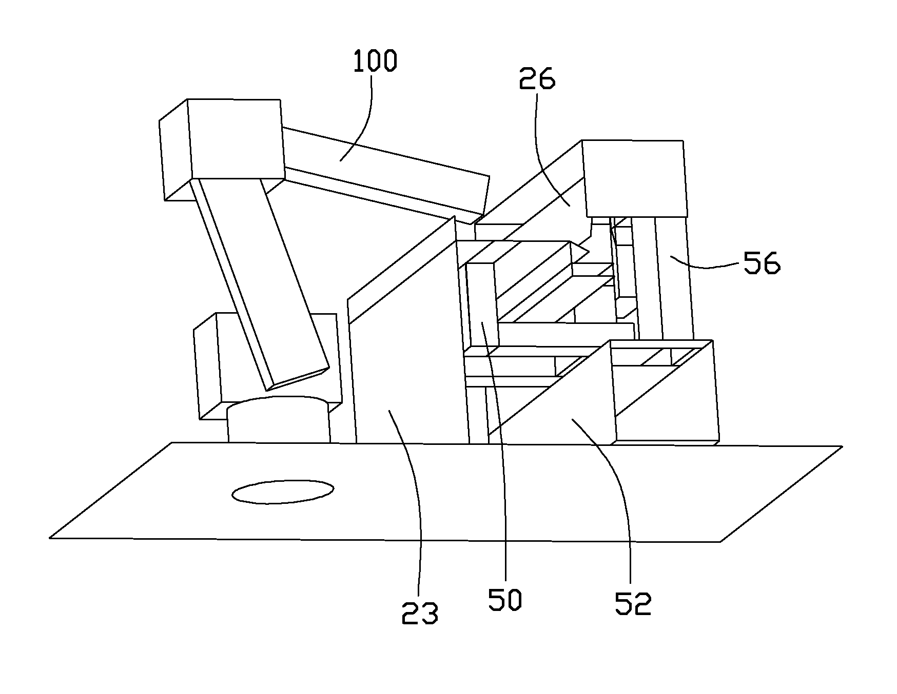
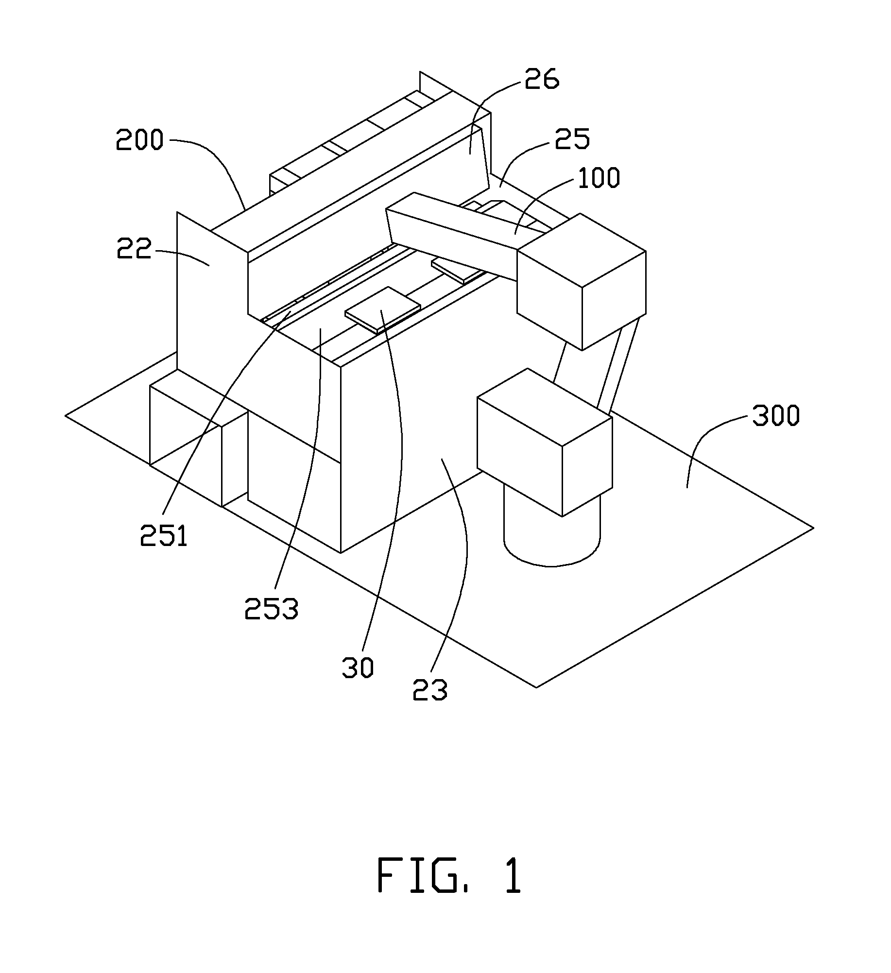
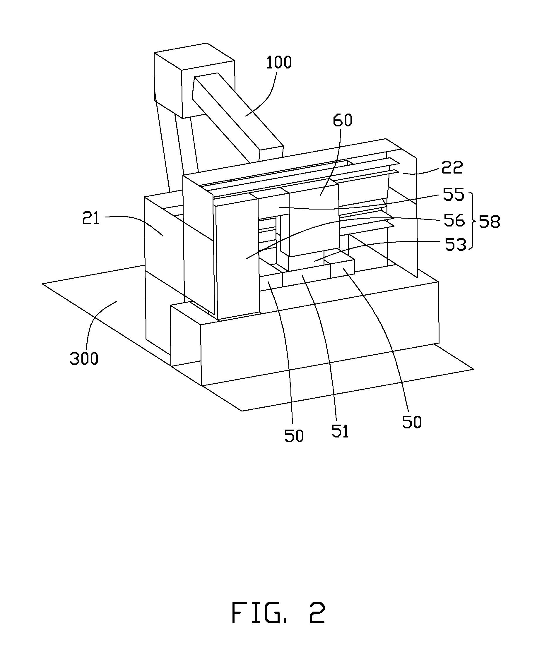
[0012]Referring to FIG. 1 and FIG. 2, a machining apparatus in accordance with an embodiment is shown. The machining apparatus comprises a robot 100 and a machine 200.

[0013]The machine 200 comprises a front plate 21, a rear plate 22, a top plate 25, a blocking plate 26, and a side plate 23 connected to the front plate 21 and the rear plate 22. In one embodiment, the front plate 21 is substantially parallel to the rear plate 22, the side plate 23 is substantially perpendicular to the front plate 21 and the rear plate 22, the top plate 25 is substantially perpendicular to the side plate 23 and the front plate 21, the blocking plate 26 is substantia...


PUM


Abstract

A machining apparatus includes a machine and robot. The machine includes a top plate, a ventilation portion, an exhaust pipe, a fan, a pipe and a jig secured to the top plate. The jig is configured for securing a workpiece to be processed. The robot is configured for polishing and cutting the workpiece. The jig defines a cutout between a top surface of the jig and the top plate. The pipe communicates with the cutout. The ventilation portion communicates with the exhaust pipe and is located between the pipe and the exhaust pipe. The fan secured to the ventilation portion. The fan guides air flows into the pipe through the cutout and discharges the air out of the machine via the ventilation portion and the exhaust pipe.

Description

BACKGROUND[0001]1. Technical Field[0002]The present disclosure relates to machining apparatuses, and particularly to a machining apparatus with a dust cleaning structure.[0003]2. Description of Related Art[0004]When workpieces are processed in a machining apparatus, a number of processes, such as polishing and cutting, may generate dust particles. If the dust particles cannot be cleaned in time, the dust particles may be collected in the machining apparatus, which may affects the appearance of the machine apparatus and health to the operators.[0005]Therefore, there is room for improvement in the art.BRIEF DESCRIPTION OF THE DRAWINGS[0006]Many aspects of the embodiments can be better understood with references to the following drawings. The components in the drawings are not necessarily drawn to scale, the emphasis instead being placed upon clearly illustrating the principles of the embodiments. Moreover, in the drawings, like reference numerals designate corresponding parts througho...

Claims


Application Information

Patent Timeline
Patent Type & Authority Applications(United States)
IPC IPC(8): B08B15/00
CPCB23Q11/0046B25J11/0065B25J11/0055B08B15/02
Inventor HUANG, GUO-HE
Owner HONG FU JIN PRECISION IND (SHENZHEN) CO LTD
Why Eureka
Try Eureka