Rack apparatus

a technology of racks and racks, applied in the field of racks, can solve problems such as affecting the appearance of workpieces

Active Publication Date: 2012-07-05
HON HAI PRECISION IND CO LTD
View PDF2 Cites 4 Cited by
  • Summary
  • Abstract
  • Description
  • Claims
  • Application Information

AI Technical Summary

Problems solved by technology

The shielding effect of the rack apparatus at the points of contact with the workpiece causes a different ampere density and a different solution density at the points of contact, resulting in marks or other defects at the contact regions of the workpiece after anodizing, which affects the appearance of the workpiece.

Method used


Image

  • Rack apparatus
  • Rack apparatus
  • Rack apparatus

Examples


Embodiment Construction

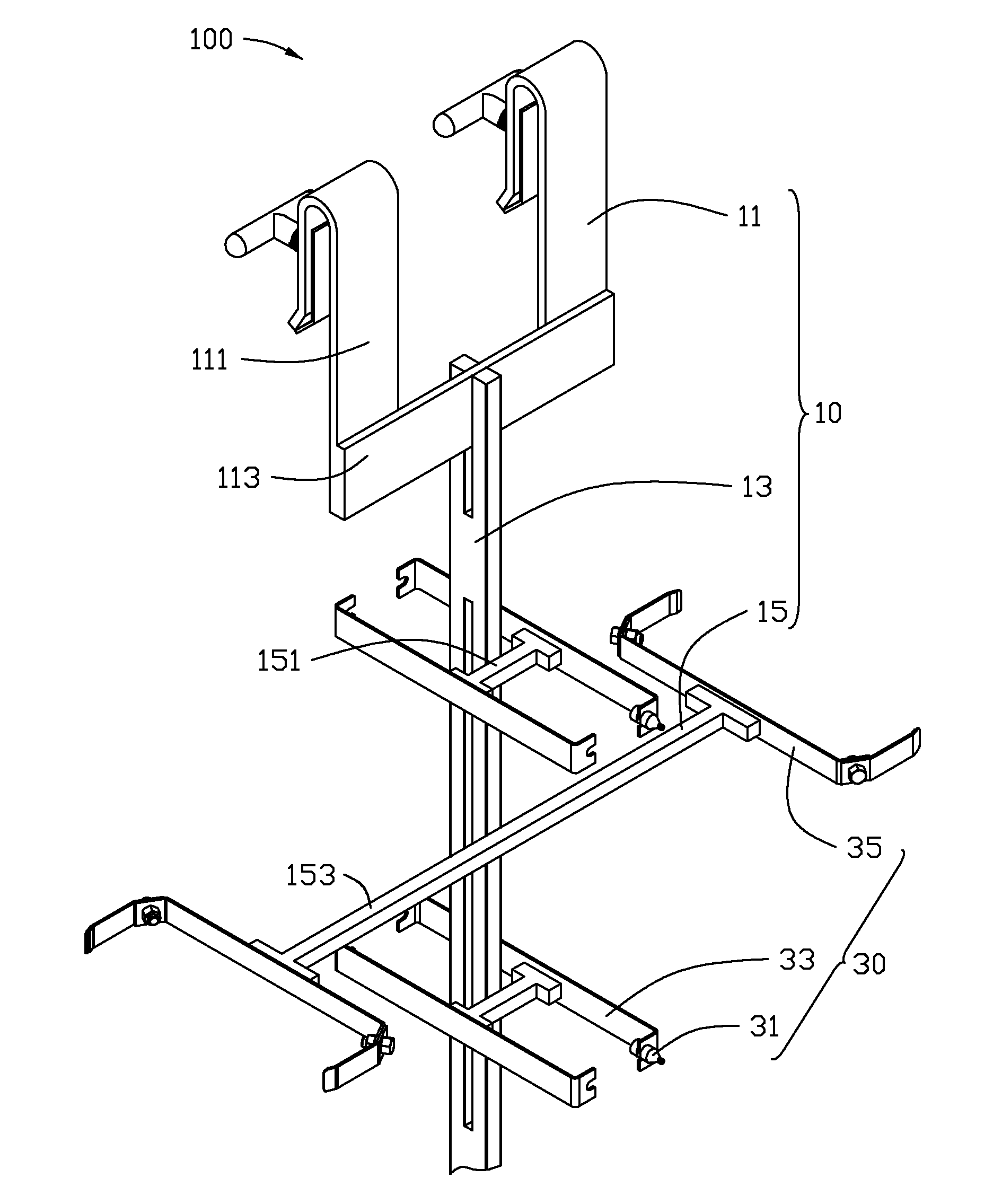
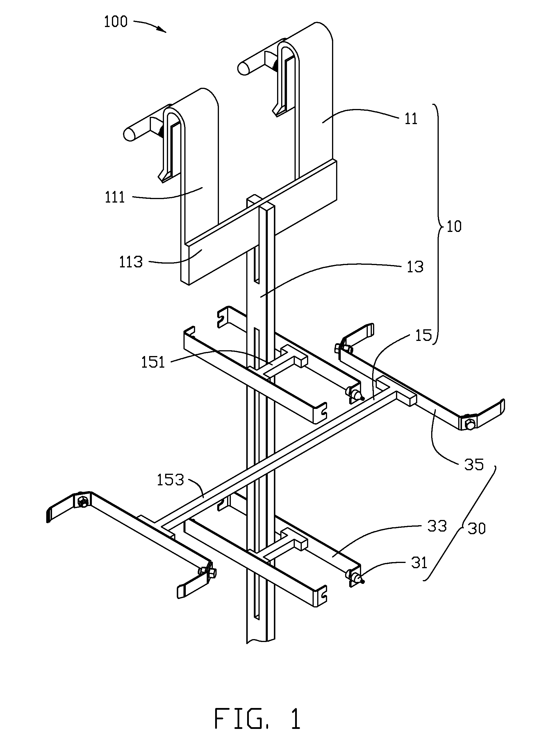
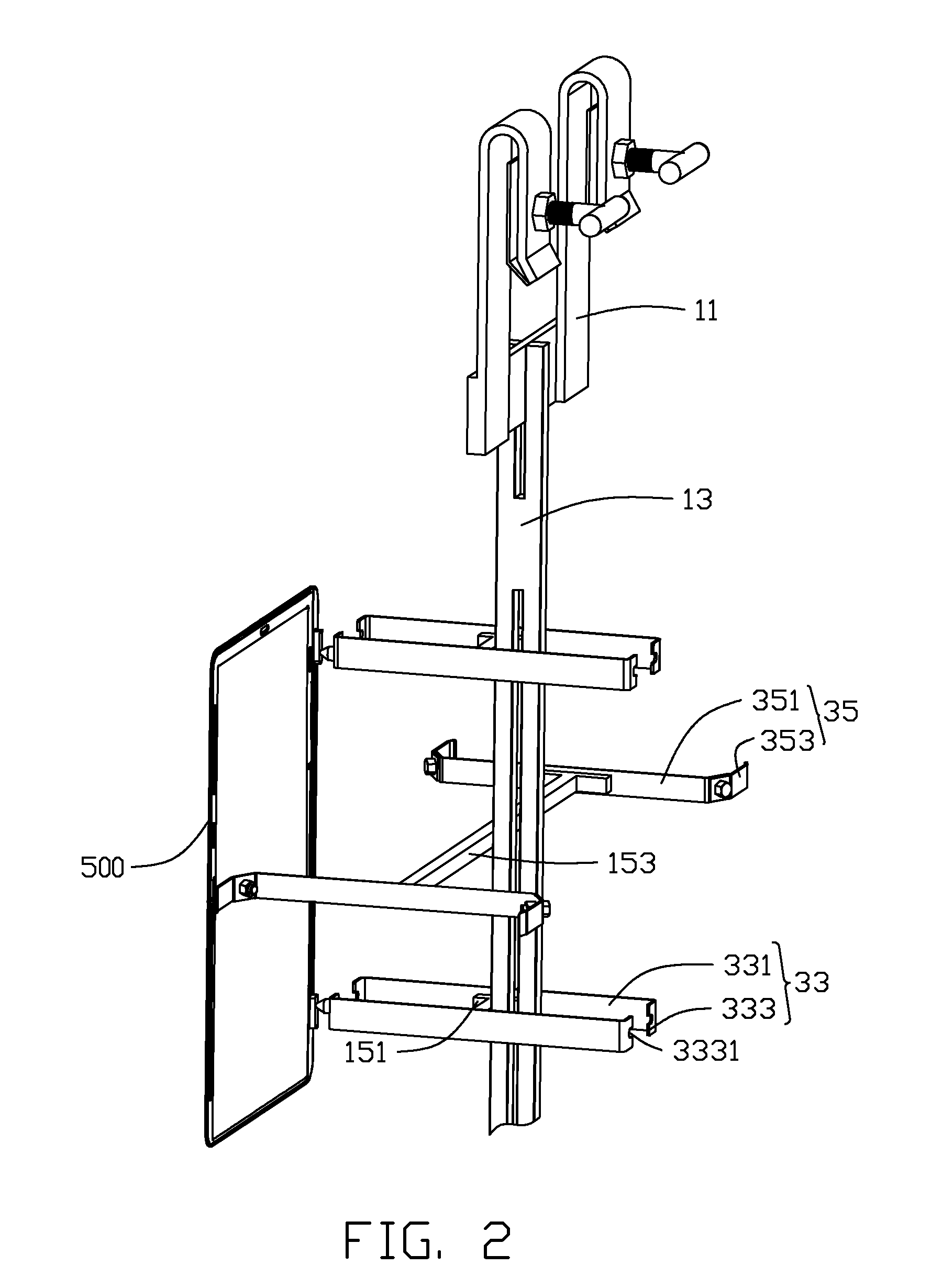
[0010]Referring to FIG. 1 and FIG. 2, an embodiment of a rack apparatus 100 includes a hanging frame 10 and a plurality of clamping assemblies 30 fixed on the hanging frame 10. The rack apparatus 100 can be used for retaining and securing workpieces during anodizing, chemical washing, and electroplating processes. In the illustrated embodiment, the rack apparatus 100 is used for retaining workpieces 500 during an anodizing process. The workpiece 500 includes two threaded holes (not labeled) defined in close proximity to an edge of the workpiece 500 and a groove (not labeled) defined in the opposing edge of the workpiece 500.

[0011]The hanging frame 10 includes a pole member 13, a hanging member 11 fixed at an end of the a pole member 13, and a plurality of supporting members 15 fixed on the pole member 13. The supporting members 15 can be arranged on the pole member 13 in a substantially equidistant manner.

[0012]The pole member 13 can be substantially in the form of a rod or bar. The...


PUM

PropertyMeasurementUnit
diameteraaaaaaaaaa
chemically durableaaaaaaaaaa
ampere densityaaaaaaaaaa

Abstract

A rack apparatus used for retaining a workpiece having at least one threaded hole, includes a hanging frame, and at least one clamping assembly fixed on the hanging frame. Each clamping assembly includes a plurality of latching members and a plurality of connecting members detachably assembled on the latching members. Each connecting member includes a screw portion. At least one screw portion is engaged in a corresponding threaded hole of the workpiece.

Description

BACKGROUND[0001]1. Technical Field[0002]The present disclosure relates to a rack apparatus, particularly to a rack apparatus used for retaining workpieces during anodizing.[0003]2. Description of Related Art[0004]Generally, a rack apparatus used for retaining workpieces during an anodizing process includes a plurality of latching hooks. The workpiece is fixed to the rack apparatus by the latching hooks engaged in latching grooves of the workpiece. The shielding effect of the rack apparatus at the points of contact with the workpiece causes a different ampere density and a different solution density at the points of contact, resulting in marks or other defects at the contact regions of the workpiece after anodizing, which affects the appearance of the workpiece. A reduction in the contact areas of the workpiece is required.[0005]Therefore, there is room for improvement in the art.BRIEF DESCRIPTION OF THE DRAWINGS[0006]Many aspects of the disclosure can be better understood with refer...

Claims


Application Information

Patent Timeline
Patent Type & Authority Applications(United States)
IPC IPC(8): C25D17/08
CPCC25D11/005C25D17/08
Inventor GUO, BINGLI, MAO-LINXU, XI-HUA
Owner HON HAI PRECISION IND CO LTD
Why Eureka
Try Eureka