Strap holding structure

a technology of holding structure and strap, which is applied in the direction of hinges, electrical apparatus casings/cabinets/drawers, manufacturing tools, etc., can solve the problems of inconvenient and uncomfortable for users to put these compact electronic devices

Inactive Publication Date: 2010-05-25
FIH (HONG KONG) LTD +1
View PDF7 Cites 4 Cited by
  • Summary
  • Abstract
  • Description
  • Claims
  • Application Information

AI Technical Summary

Benefits of technology

[0005]In a typical structure of holding electronic devices, it is inconvenient and uncomfortable for users to put these compact electronic devices into their pockets or hang them on their belts. Another conventional structure for holding electronic devices is a holder (i.e., an eyelet or the like) positioned in an electronic device so that a strap may be tied to the holder and hung around the neck. The holder is generally received in a receiving portion of the electronic device. When the holder has an axial force exerted on it, the holder can move axially off from the electronic device so that this structure might not hold the holder steadily in the receiving portion of the electronic device. In addition, this holder needs a screw to attach to the electronic device. Owing to the screw being positioned outside the electronic device, the screw will affect the appearance of the electronic device.

Problems solved by technology

In a typical structure of holding electronic devices, it is inconvenient and uncomfortable for users to put these compact electronic devices into their pockets or hang them on their belts.

Method used


Image

  • Strap holding structure
  • Strap holding structure
  • Strap holding structure

Examples


Embodiment Construction

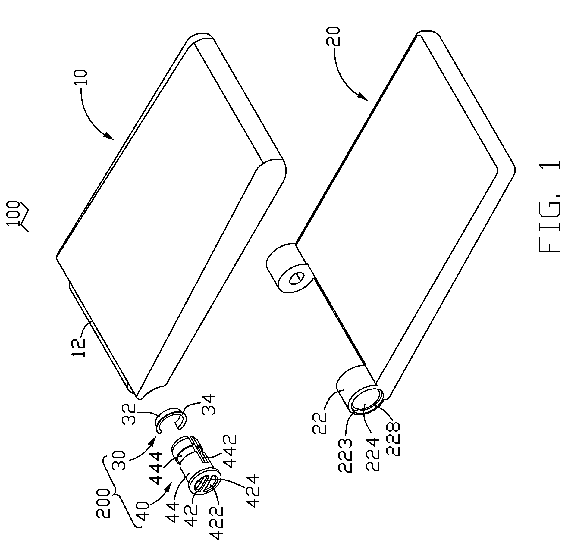
[0016]Referring now to the drawings in detail, FIG. 1 shows a strap holding structure for an electronic device such as a mobile phone in accordance with one embodiment of the present invention. In an exemplary application, the strap holding structure is incorporated in a mobile phone 100.

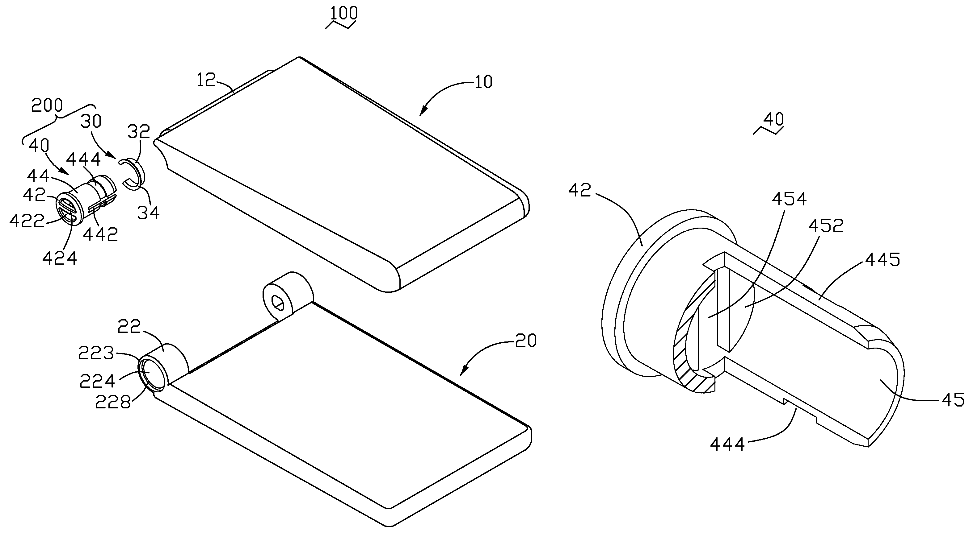
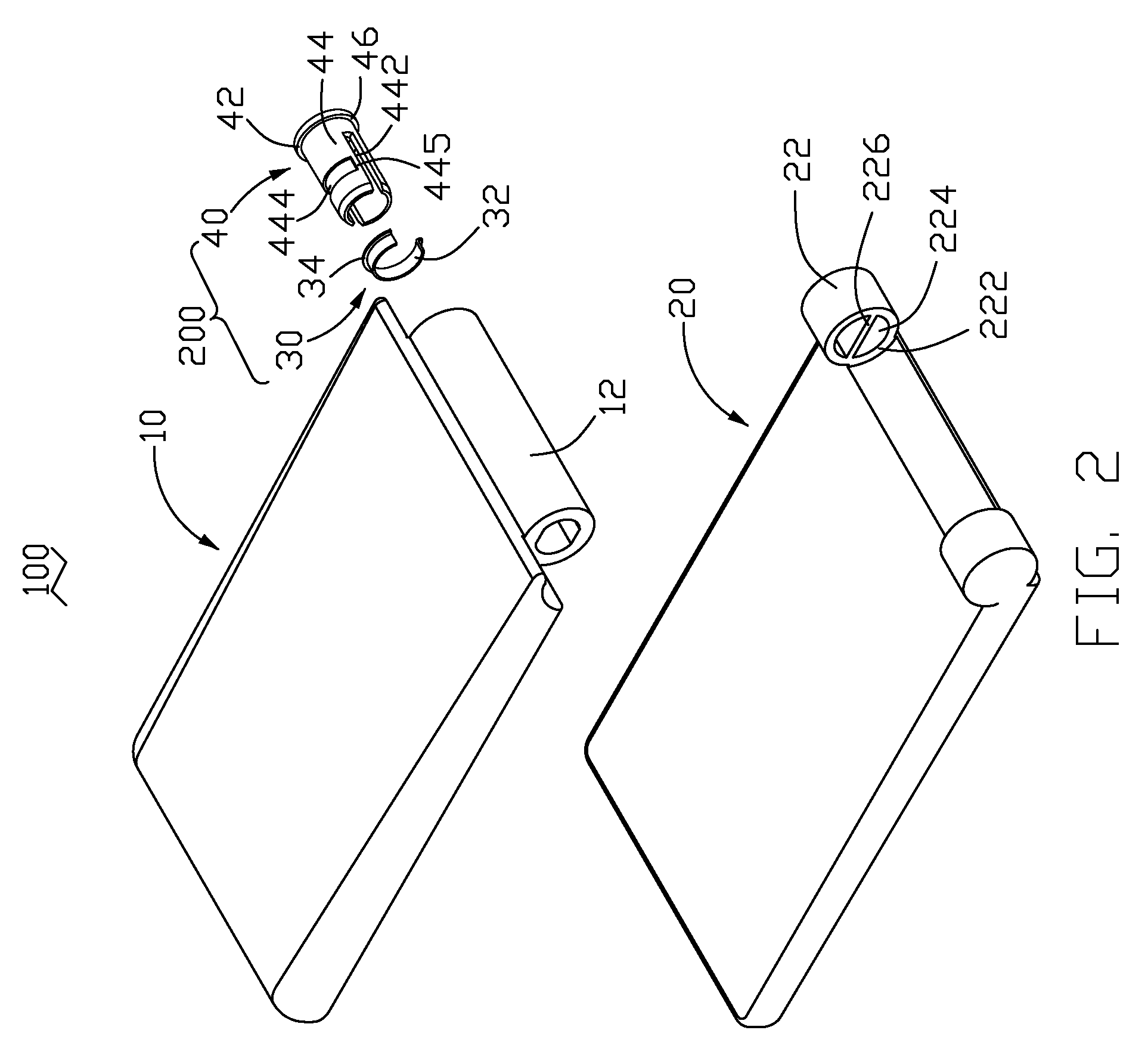
[0017]Referring also to FIG. 2, the mobile phone 100 includes a cover 10, a main body 20 and a strap holding structure 200. The cover 10 and the main body 20 are rotatably interconnected through a hinge assembly for switching the mobile phone 100 between an in-use position and a closed position. The strap holding structure 200 may be attached to the cover 10 and the main body 20. The strap holding structure 200 includes a latching element 30 and a strap holder 40.

[0018]Referring also to FIG. 3, the cover 10 has a hollow barrel 12 formed at one end thereof. The barrel 12 has an end wall 122 at a distal thereof. A C-shaped groove 124 is defined in the end wall 122. The main body 20 has a cylindrical k...


PUM


Abstract

A strap holding structure (200) for an electronic device (100), which includes a body (20), a cover (10). The body has a knuckle (22) formed at one end thereof. The knuckle has a middle board (226) formed therein. The cover has a barrel (12) formed at one end. The strap holding structure includes a latching element (30) and a strap holder (40). The latching element is attached to the cover at one end. The strap holder has a pole (424) at a first end of the strap holder. A groove (444) is circumferentially defined in an outer wall of the strap holder and two notches (442) are axially defined in the outer wall thereof. The strap holder is engaged in the knuckle and the barrel. The latching element is received in the groove and the middle board is received in the notches.

Description

BACKGROUND OF THE INVENTION[0001]1. Field of the Invention[0002]The present invention relates to strap holding structures and, particularly, to a strap holding structure for compact electronic devices such as portable telephones, portable computers, and so on.[0003]2. Discussion of the Related Art[0004]Compact electronic devices, such as portable telephones, internet wireless communicators, CD players, MP3 music players, mini electronic games, etc., have become more and more popular.[0005]In a typical structure of holding electronic devices, it is inconvenient and uncomfortable for users to put these compact electronic devices into their pockets or hang them on their belts. Another conventional structure for holding electronic devices is a holder (i.e., an eyelet or the like) positioned in an electronic device so that a strap may be tied to the holder and hung around the neck. The holder is generally received in a receiving portion of the electronic device. When the holder has an ax...

Claims


Application Information

Patent Timeline
Patent Type & Authority Patents(United States)
IPC IPC(8): H05K7/16
CPCH04M1/0216A45F5/00Y10T16/522A45F2200/0516
Inventor WANG, JUNTU, HSIAO-HUAGE, PENG-JINYANG, GANGSUN, YONG-HUI
Owner FIH (HONG KONG) LTD
Why Eureka
Try Eureka