Compact circular polarization antenna system with reduced cross-polarization component

a circular polarization antenna and component technology, applied in the field of antennas, can solve the problems of increasing the antenna dimension, reducing the coupling and excitation level of the passive radiator, and affecting the operation efficiency of the antenna

Active Publication Date: 2013-12-26
TOPCON POSITIONING SYST INC
View PDF4 Cites 12 Cited by
  • Summary
  • Abstract
  • Description
  • Claims
  • Application Information

AI Technical Summary

Benefits of technology

[0010]An antenna system for receiving navigation satellite signals is proposed, comprising a patch radiator consisting of a radiating patch disposed over a ground plane which is excited by, for example, exciting electric pins or slots, from a connected power circuit of the MP radiator, and a horizontal loop ra...

Problems solved by technology

However, this results in increasing antenna dimensions.
This, in turn, causes reduction in their cou...

Method used


Image

  • Compact circular polarization antenna system with reduced cross-polarization component
  • Compact circular polarization antenna system with reduced cross-polarization component
  • Compact circular polarization antenna system with reduced cross-polarization component

Examples


Embodiment Construction

[0039]Reference will now be made in detail to the embodiments of the present invention, examples of which are illustrated in the accompanying drawings.

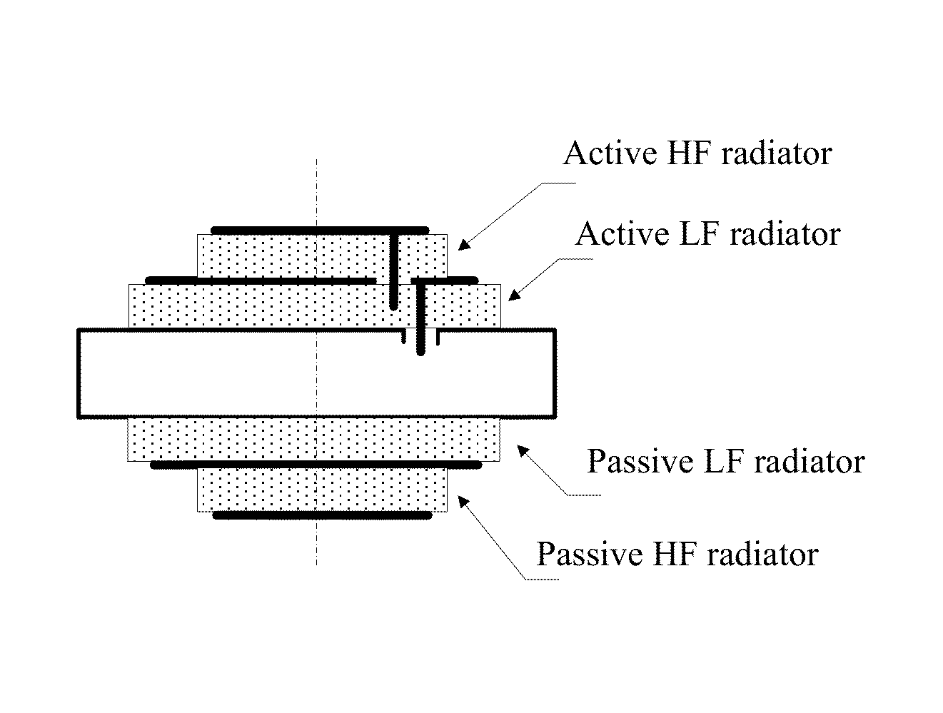
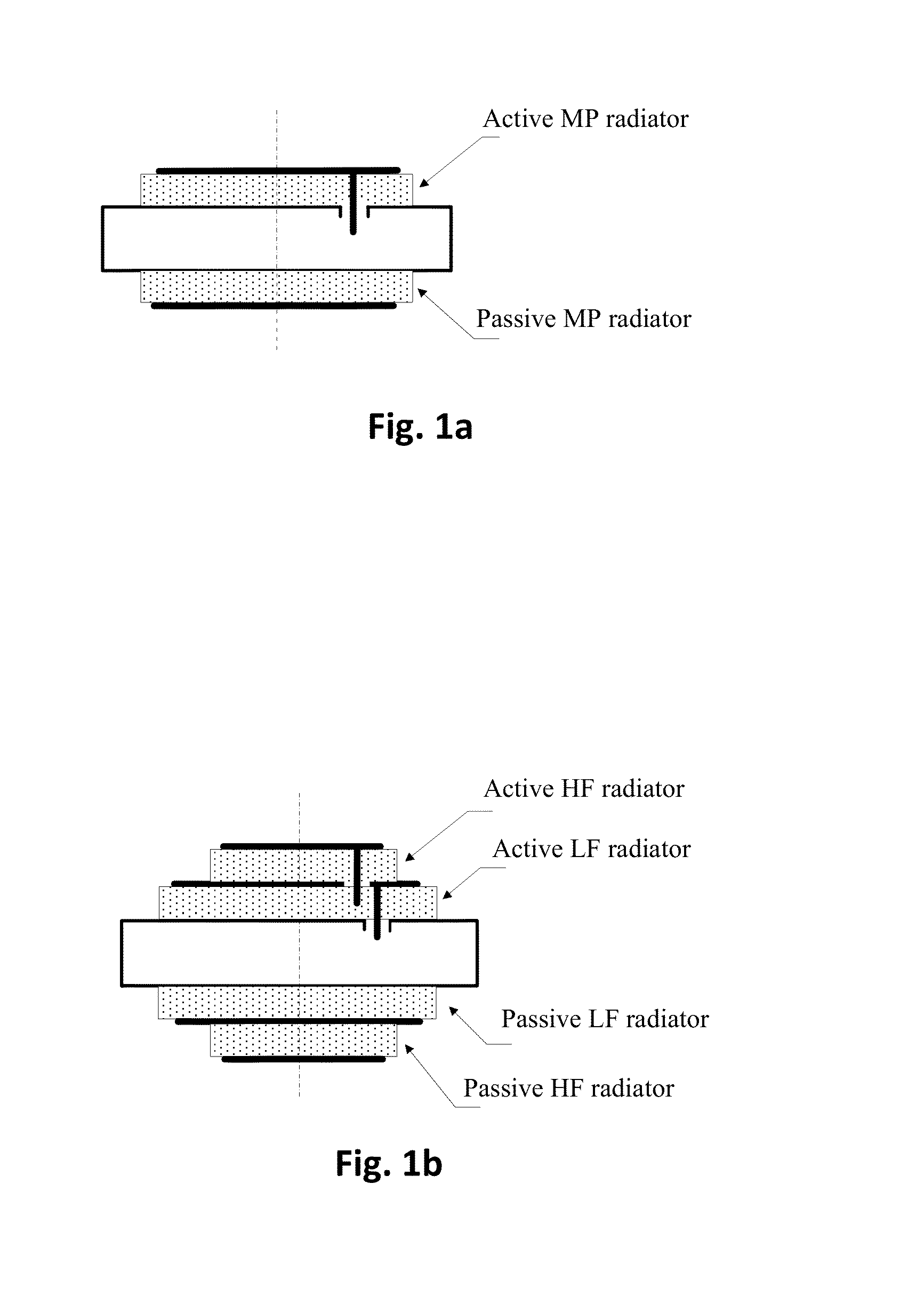
[0040]This described apparatus suppresses LHCP field in a wide angle sector of the rear hemisphere and reduces overall antenna dimensions. This is achieved by an antenna design comprising a MP radiator and an additional radiator in the form of a conductive loop disposed around and coaxially with the main MP radiator. Suppression of radiation in the rear hemisphere is the result of field interference of two radiators. The dimensions of the antenna are smaller than that of the conventional design.

[0041]Below there are given variants of antenna design with active and passive excitation of the loop radiator.

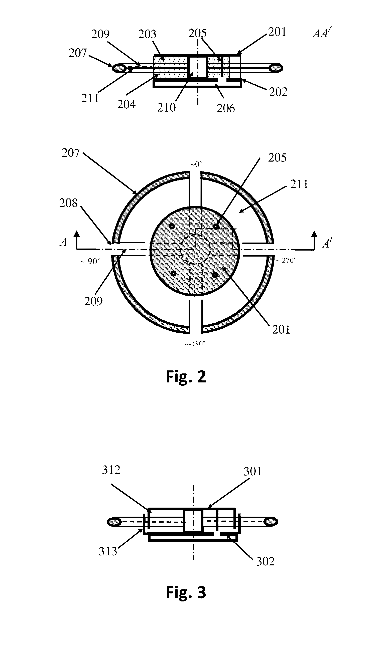
[0042]FIG. 2 shows an antenna design with an actively-excited loop radiator. The design includes a MP radiator, which comprises radiating patch 201 disposed above flat metal ground plane 202. Between them there is a layer filled with a...


PUM


Abstract

Patch antennas for signals of global navigation satellite systems (GNSS) are described. A compact antenna system reduces directional diagram level in the rear hemisphere primarily for cross-polarized (left hand circularly-polarized) component. It can be used for reducing multipath reception. The antenna receives GNSS signals and includes a patch circularly-polarized radiator consisting of a radiating patch, a ground plane under it and a loop radiator coaxially located around the patch radiator. The loop radiator is excited by a separate power circuit or by a passive method where LHCP waves of MP and loop radiators in the rear hemisphere would be anti-phase added. A dual-band antenna system includes an active HF radiator, under which there is an active LF radiator under which there is a passive LF radiator, a loop HF radiator being coaxially located around the active HF radiator.

Description

CROSS-REFERENCE TO RELATED APPLICATIONS[0001]This application is a U.S. National Phase of PCT / RU2012 / 000446, filed on Jun. 7, 2012, which is incorporated by reference herein in its entirety.BACKGROUND[0002]1. Field of the Invention[0003]The present invention relates to antennas, in particular, to patch antennas used in global navigation satellite systems (GNSS).[0004]2. Description of the Related Art[0005]Patch antenna systems are used in different radio electronic devices. They are widely applicable in ground satellite navigation systems (GPS, GLONASS, Galileo etc.), with the help of which a position of an object can be quickly and accurately determined at any point of the world. One of the main reasons for reduced GNSS positioning accuracy of land objects is related to receiving not only the line-of-sight satellite signal but also signals reflected from surrounding objects, and especially from the Earth's surface. The strength of such signals depends directly on the antenna's dire...

Claims


Application Information

Patent Timeline
IPC IPC(8): H01Q5/01H01Q5/10
CPCH01Q5/01H01Q7/00H01Q9/0414H01Q21/29H01Q1/48H01Q9/0428H01Q21/28
Inventor TATARNIKOV, DMITRY VITALIEVICHASTAKHOV, ANDREY VITALIEVICH
Owner TOPCON POSITIONING SYST INC
Why Eureka
Try Eureka