Power supply device

a power supply device and power supply technology, applied in the direction of power conversion systems, dc-dc conversion, instruments, etc., can solve the problems of rising device cost, and achieve the effects of low cost, high efficiency, and low cost power supply

Inactive Publication Date: 2014-04-17
FUJI ELECTRIC CO LTD
View PDF4 Cites 21 Cited by
  • Summary
  • Abstract
  • Description
  • Claims
  • Application Information

AI Technical Summary

Benefits of technology

[0054]According to the invention, it is possible to realize a highly efficient, small-sized, low cost power supply device by reducing loss caused by a heretofore known bypass diode that bypasses a step-up chopper, and simplifying the drive power supply of a series circuit of MOSFETs connected instead of the bypass diode.

Problems solved by technology

However, the voltage drop of the diode 101 is already in the region of 1V or less, and when using MOSFETs with the same breakdown voltage and specifications as, for example, the switching device 7 in order to obtain the advantage of reducing the voltage drop sufficiently with respect to the voltage drop of the diode 101, it is necessary that the number of parallel MOSFETs is equivalent to the number of switching devices 7, which leads to a rise in the device cost.

Method used


Image

  • Power supply device
  • Power supply device
  • Power supply device

Examples


Embodiment Construction

[0061]Hereafter, a description will be given, based on the drawings, of embodiments of the invention.

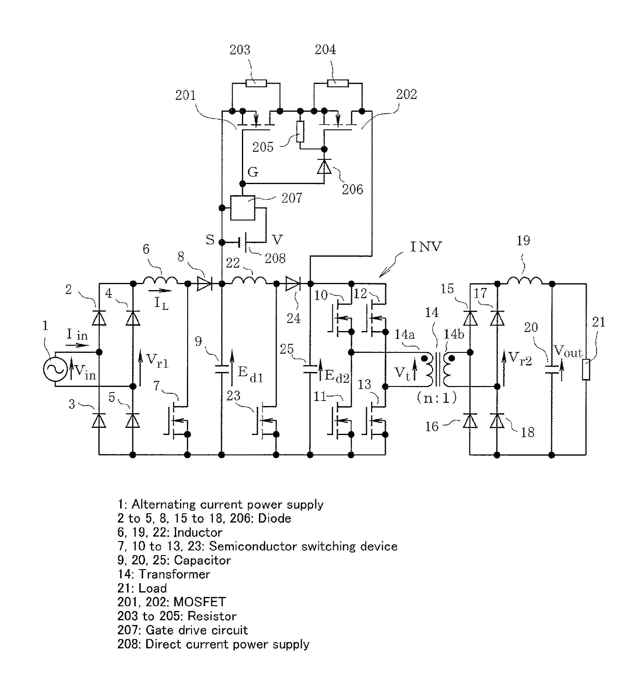
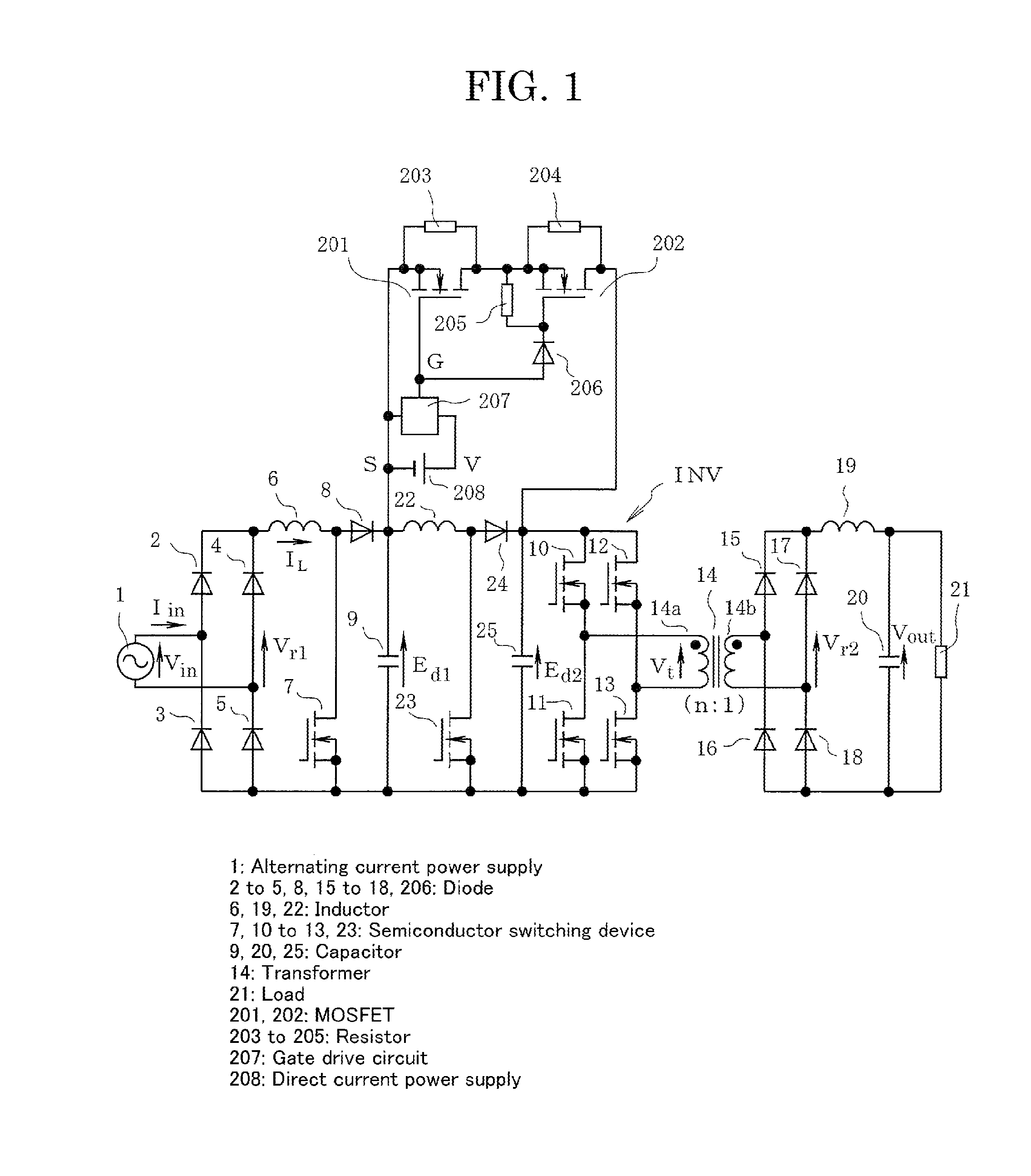
[0062]FIG. 1 is a circuit diagram showing a first embodiment of the invention. The first embodiment is such that the circuit described hereafter is added to the circuit shown in FIG. 5. The same reference signs are given to portions the same as those in FIG. 5, and a description thereof is omitted.

[0063]That is, MOSFETs 201 and 202 are connected in series between the cathode of a diode 8 and the cathode of a diode 24, and resistors 203 and 204 with equal resistance values are connected between the source electrode and gate electrode of the MOSFETs 201 and 202 respectively. Also, 207 is a gate drive circuit, and a direct current power supply 208 is connected to both ends of the gate drive circuit 207. Agate drive signal G output from the gate drive circuit 207 is input directly into the gate electrode of the one MOSFET 201, and input via a diode 206 into the gate electrode of the othe...


PUM


Abstract

A power supply device includes a first semiconductor switching device for controlling an alternating input current waveform, a smoothing capacitor to which a rectified voltage is applied, and an inverter that converts the rectified voltage into alternating current via a step-up chopper. The step-up chopper includes an inductor and a diode connected between the smoothing capacitor and inverter, and a second semiconductor switching device connected to the inductor and diode. The power supply device further includes an instantaneous voltage drop compensation function whereby the energy of the smoothing capacitor is supplied by an operation of the step-up chopper to the inverter when there is an instantaneous voltage drop in an alternating current power supply voltage. MOSFETs with a breakdown voltage lower than that of the first semiconductor switching device are connected between terminals of the step-up chopper, thus further reducing loss in comparison with when a bypass diode is used.

Description

BACKGROUND OF THE INVENTION[0001]1. Field of the Invention[0002]The present invention relates to a power supply device having a function of compensating for an instantaneous voltage drop in an alternating current power supply voltage, and specifically, relates to technology for increasing the efficiency and reducing the size of the device.[0003]2. Description of the Background Art[0004]FIG. 3 shows first heretofore known technology of a power supply device having a function of compensating for an instantaneous voltage drop in an alternating current power supply voltage.[0005]In FIG. 3, reference sign 1 is an alternating current power supply, and a rectifier circuit formed of diodes 2 to 5 is connected to both ends of the alternating current power supply. An inductor 6 and a semiconductor switching device 7, such as a MOSFET, are connected in series to either end of a series circuit of the diodes 4 and 5, and a diode 8 and smoothing capacitor 9 are connected in series to either end o...

Claims


Application Information

Patent Timeline
Patent Type & Authority Applications(United States)
IPC IPC(8): H02M3/335H02M1/00
CPCH02M3/335H02M3/158H02M1/007H02M3/33573
Inventor YAMADA, RYUJITAWADA, NOBUYUKI
Owner FUJI ELECTRIC CO LTD
Why Eureka
Try Eureka