Device and method of treating heart valve malfunction

a technology of heart valve and device, applied in the field of instruments, can solve the problems of abnormal leaking of blood from the left ventricle back into the left atrium, mitral valve remaining partially open during ventricular contraction, and mitral valve regurgitation

Active Publication Date: 2014-05-22
CORQUEST MEDICAL
View PDF10 Cites 16 Cited by
  • Summary
  • Abstract
  • Description
  • Claims
  • Application Information

AI Technical Summary

Benefits of technology

[0014]Also, the exteriorly concentric introductory sheath is movable relative to and along the length of the chord so as to accommodate proper and intended placement and anchoring of the chord within the heart chamber. Therefore, the sheath is movable with the chord into and through predetermined portions of the heart chamber and movable relative to the chord after proper anchoring, securing and/or intended placement of the chord within the heart chamber. Accordingly, the instrument assembly of the present invention also includes an anchor secured to an outer or distal end of the chord. The anchor may also be sufficiently sharpened, pointed or otherwise configured to penetrate an intended heart valve leaflet, such as a prolapsing leaflet of the mitral valve. Further, the penetration and passage of the anchor, the chord, and the introductory sheath substantially through the predetermined valve leaflet may thereby be facilitated.
[0015]When properly positioned, the anchor is structured to be secured to a substantially opposing portion of the heart wall, such as the ventricular wall associated with the left ventricle and/or the papillary

Problems solved by technology

A dysfunction of any of these components of the mitral valve can cause “mitral regurgitation”.
This results in abnormal leaking of blood from the left ventricle back into the left atrium, through the mitral valve, when the left ventricle contracts and is a condition known as “mitral regurgitation”.
However, when the mitral valve malfunctions, due to various cardiac diseases, the leaflets are no longer coapting resulting in the mitral valve remaining partially open during ventricular contraction.
When the mitral valve

Method used


Image

  • Device and method of treating heart valve malfunction
  • Device and method of treating heart valve malfunction
  • Device and method of treating heart valve malfunction

Examples


Embodiment Construction

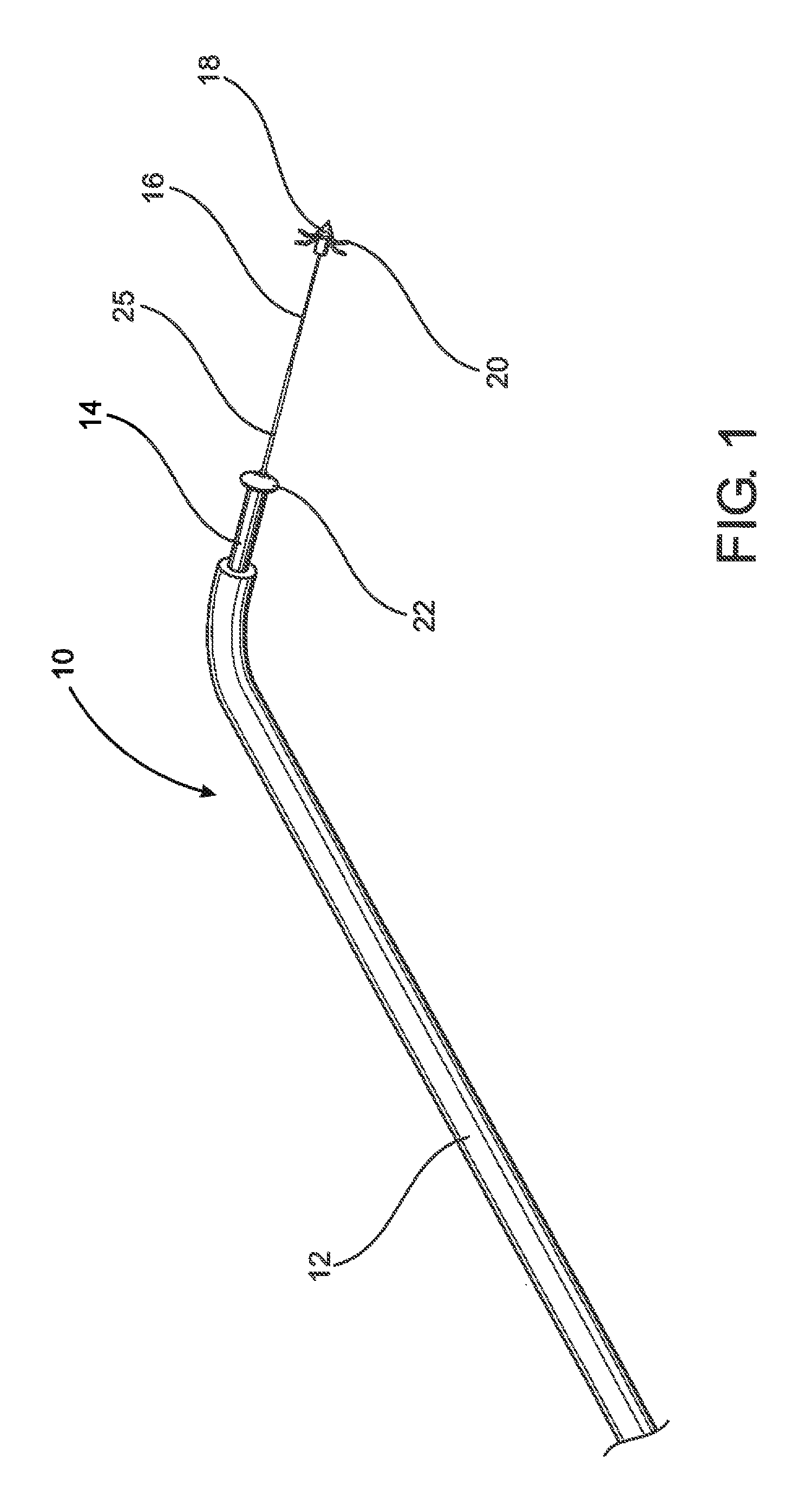
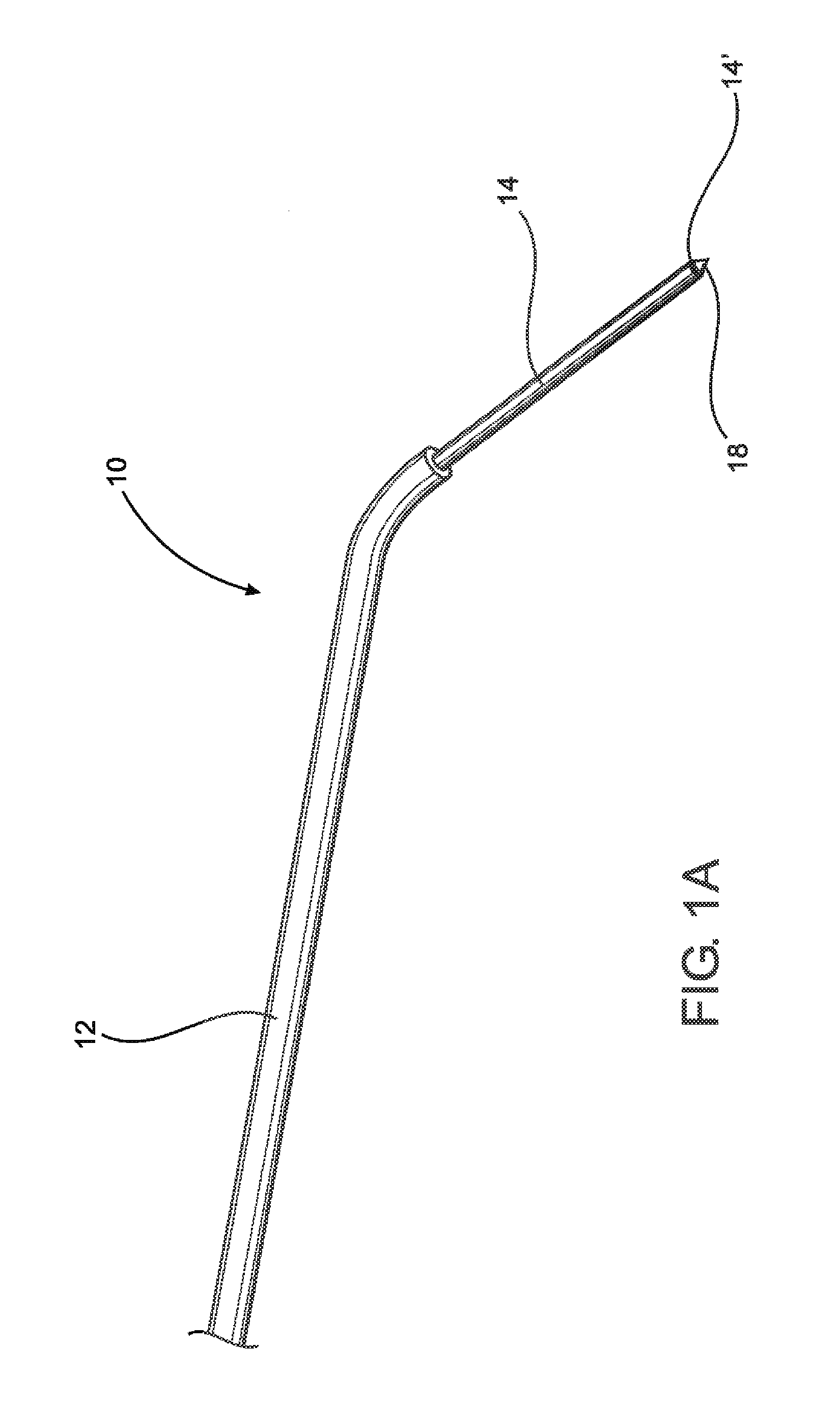
[0045]As represented in the accompanying drawings and with specific reference to FIGS. 1 and 1A, the instrument assembly of the present invention is schematically and generally indicated as 10 and is used for the treatment of heart valve malfunction generally and more specifically for the treatment of mitral regurgitation. As such, the instrument assembly 10 includes an elongated delivery catheter or tube 12 having a hollow interior and structured to deliver operative portions of the instrument assembly 10 to the treatment site within the heart of a patient. As such, the elongated delivery catheter or tube 12 is dimensioned and configured to enter the chest cavity through appropriate introduction instrumentation. The delivery tube 12 is formed of a material and / or includes positioning structure or linkage incorporated therein which facilitates the maneuvering or steering thereof to a point at least generally exterior the heart and more specifically the atrial wall of the left atrium...


PUM


Abstract

An assembly and method for treating heart valve malfunction including mitral regurgitation wherein an elongated chord is movably disposed within an introductory sheath and an anchor is secured to a distal end thereof. The sheath and the chord are introduced into the heart chamber and penetrate and pass through the anterior mitral valve leaflet and preferably through the mitral valve orifice. The sheath and the chord are then extended transversely across the heart chamber and the distal end of the chord is anchored to an opposing portion of the heart wall. The sheath is withdrawn back along the length of the anchored chord through the anterior mitral valve leaflet and the proximal end of the chord is secured to the valve leaflet. The chord is secured under sufficient tension to maintain an intended positioning of the valve leaflet to overcome mitral regurgitation.

Description

CLAIM OF PRIORITY[0001]The present application is a continuation in part application of currently pending patent application having Ser. No. 13 / 691,087 and a filing date of Nov. 30, 2012, which is based on a claim of priority under 35 U.S.C. Section 119(e) to a provisional patent application that is currently pending in the U.S. Patent and Trademark Office, namely, that having Ser. No. 61 / 729,152 and a filing date of Nov. 21, 2012, and which is incorporated herein by reference in its entirety.BACKGROUND OF THE INVENTION[0002]1. Field of the Invention[0003]The present invention is directed to an instrument assembly and method of use and application in the treatment of heart valve malfunction. In more specific terms the instrument assembly is specifically adapted to treat mitral regurgitation by means of a direct entry of the instrument through the atrial wall rather than through the vascular system, in order to apply sufficient tension to a prolapsing leaflet, including the anterior ...

Claims


Application Information

Patent Timeline
IPC IPC(8): A61F2/24
CPCA61F2/2427A61F2/2457A61B17/0401A61B17/0482A61B17/0643A61B17/068A61B2017/0409A61B2017/0437A61B2017/045A61B2017/0464A61F2/2466
Inventor DE CANNIERE, DIDIERMOUREAUX, CHRISTOPHE
Owner CORQUEST MEDICAL
Why Eureka
Try Eureka