

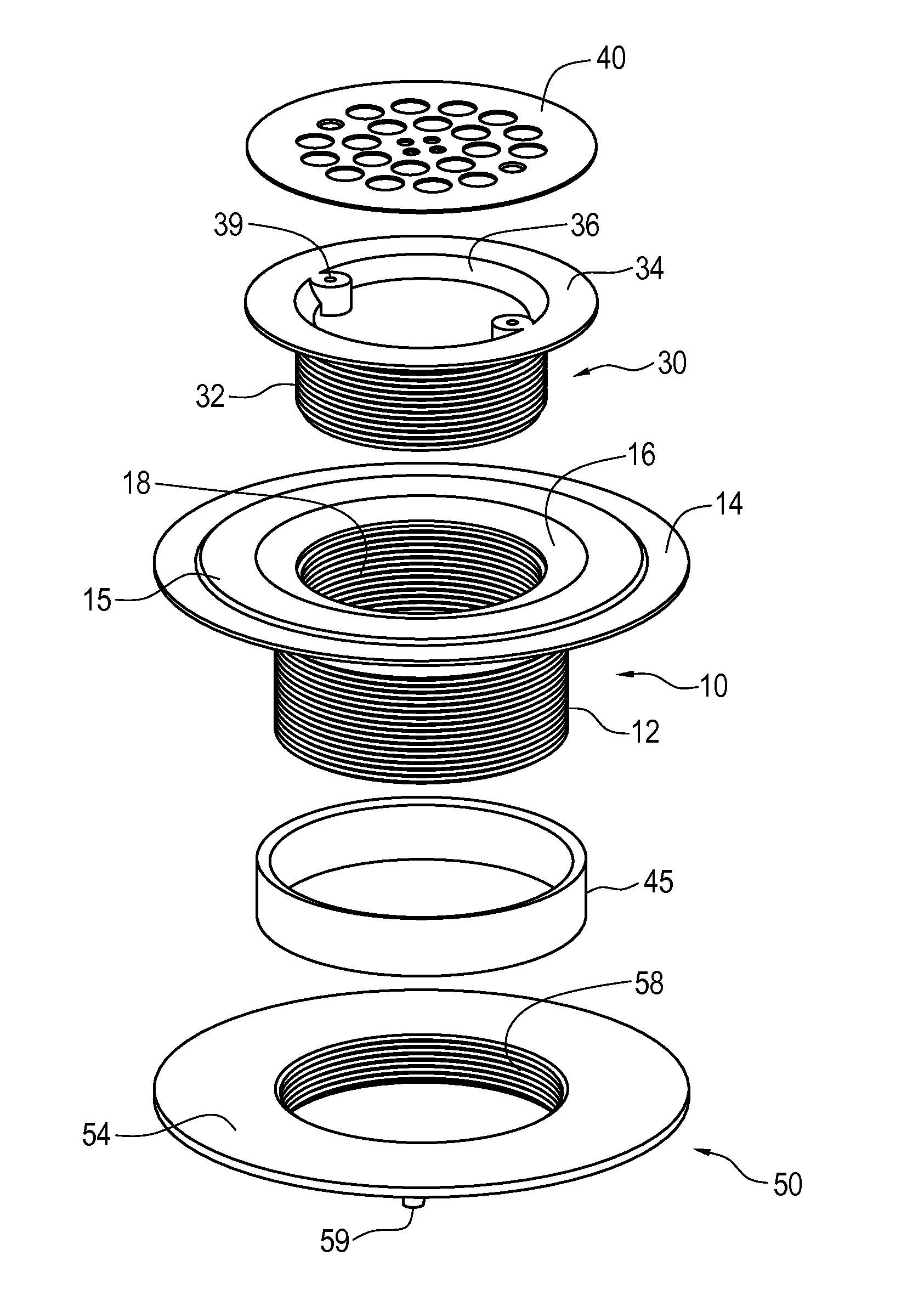
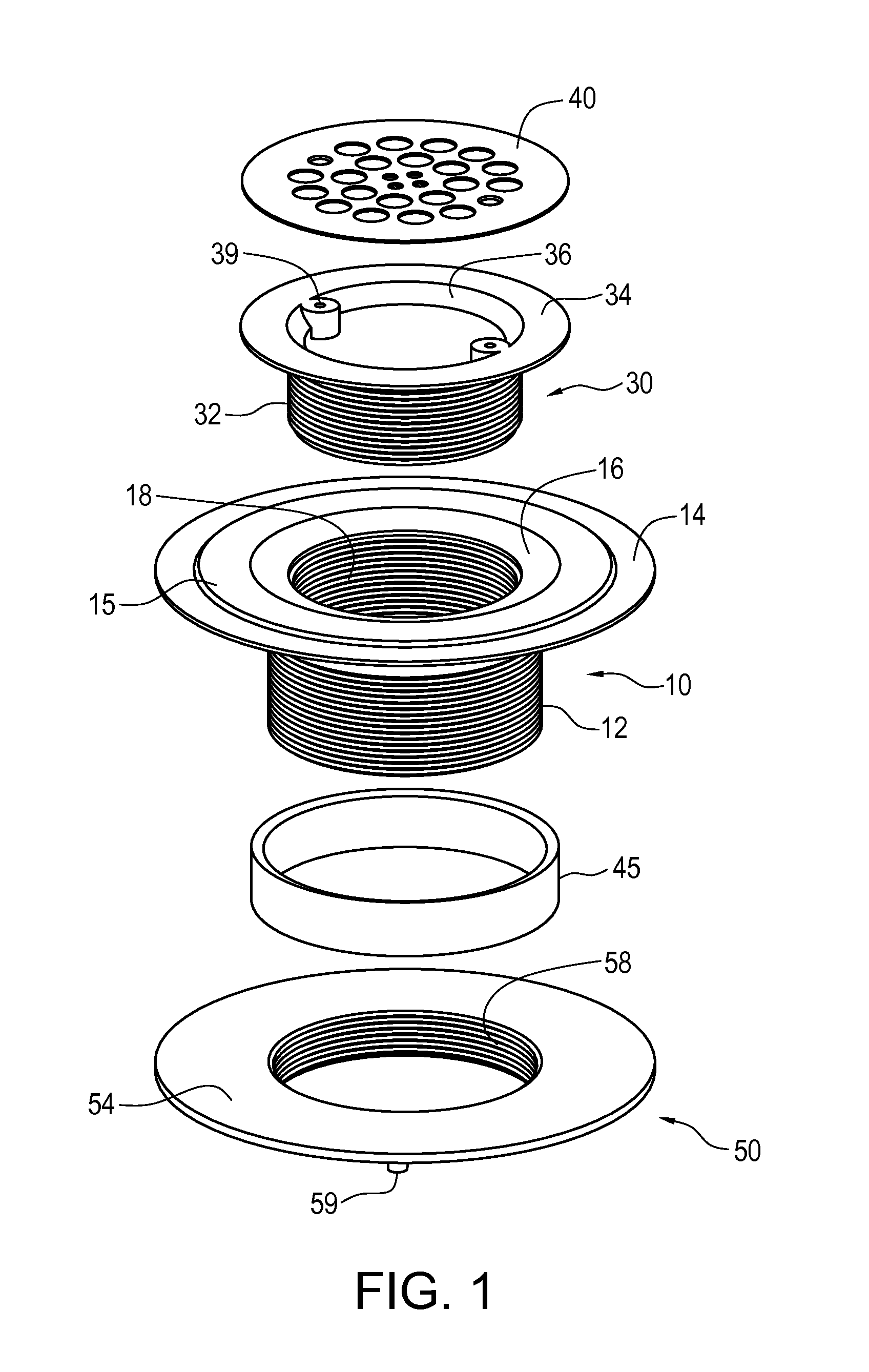
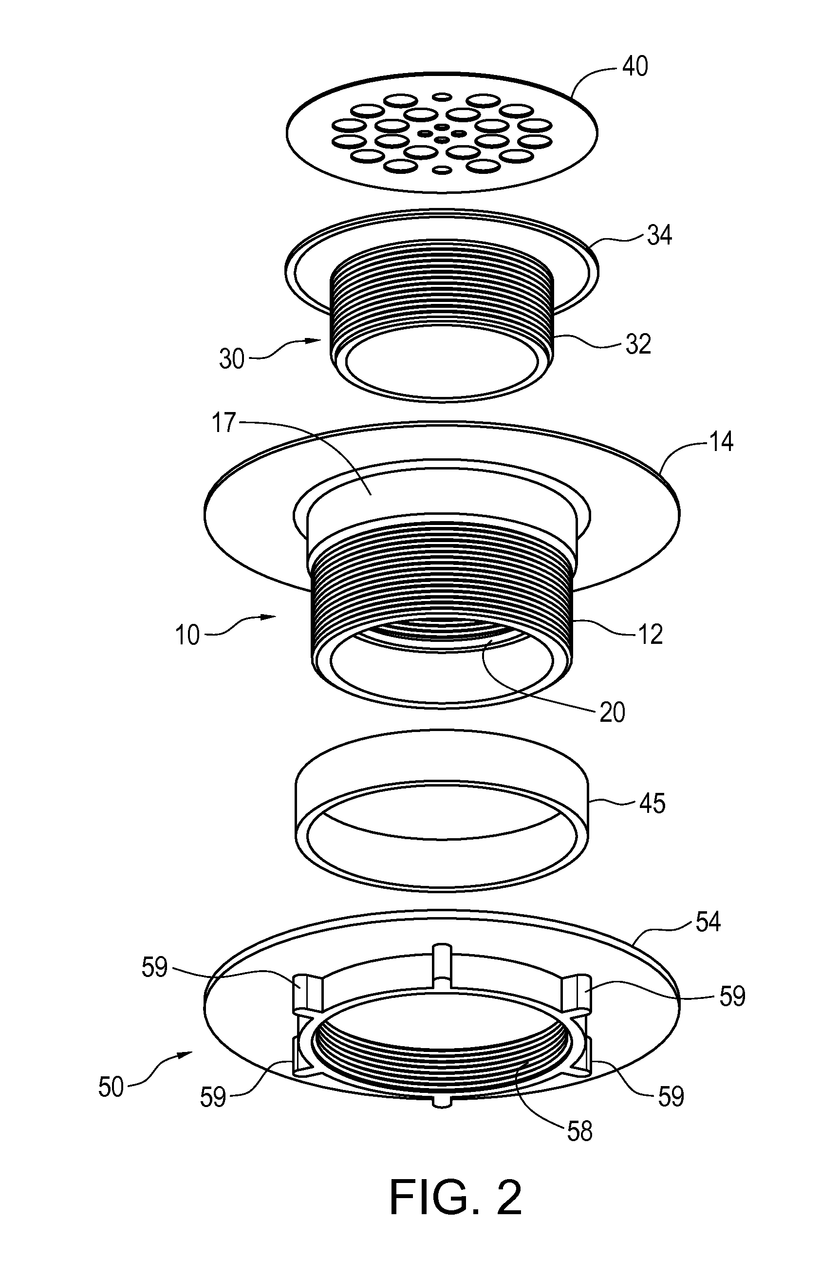
Compression drain with adjustable-height grate
- Summary
- Abstract
- Description
- Claims
- Application Information
AI Technical Summary
Benefits of technology
Problems solved by technology
Method used
Image

Examples
Embodiment Construction
)
[0017]Before describing in detail exemplary embodiments that accord with the present invention, it should be observed that the embodiments reside primarily in combinations of apparatus components and processing steps related to implementing a compression drain for use with a preformed floor in which the height of the drain grate can be adjusted relative to said floor, and which positively locates the drain housing relative to the subfloor / waste water drain pipe. Accordingly, the apparatus and method components have been represented where appropriate by conventional symbols in the drawings, showing only those specific details that are pertinent to understanding the embodiments of the present invention so as not to obscure the disclosure with details that will be readily apparent to those of ordinary skill in the art having the benefit of the description herein.
[0018]In this document, relational terms, such as “first” and “second,”“top” and “bottom,” and the like, may be used solely ...
PUM
 Abstract
Description
Claims
Application Information