Sensor for detecting acceleration and angular velocity

Active Publication Date: 2008-11-27
WAKO CO LTD
View PDF34 Cites 29 Cited by
  • Summary
  • Abstract
  • Description
  • Claims
  • Application Information

AI Technical Summary

Benefits of technology

[0107]In a sensor according to the present invention, there is provided a weight body, a pedestal, and a flexible connection for connecting the weight body and the pedestal. An applied acceleration or angular velocity is detected by detecting a displacement of the weight body with respect to the pedestal. In addition, the acceleration is detected based on the change in the electrical resistance of a piezoresistive element formed in the flexible connection, while the angular velocity is detected through a piezoelectric element formed in the flexible connection. Since the piezoresistive element and the piezoelectric element are both formed in a flexible connection, it is p

Problems solved by technology

However, as for acceleration detection, dynamic acceleration (acceleration of a time-varying amount in a time-varying direction) can be detected, but static acceleration (constant acceleration due to, for example, gravity) cannot be detected in this type of sensor.
However, if the applied force is constant, no charge is to be generated

Method used


Image

  • Sensor for detecting acceleration and angular velocity
  • Sensor for detecting acceleration and angular velocity
  • Sensor for detecting acceleration and angular velocity

Examples


Example

Basic Structure of the Sensor According to the First Embodiment

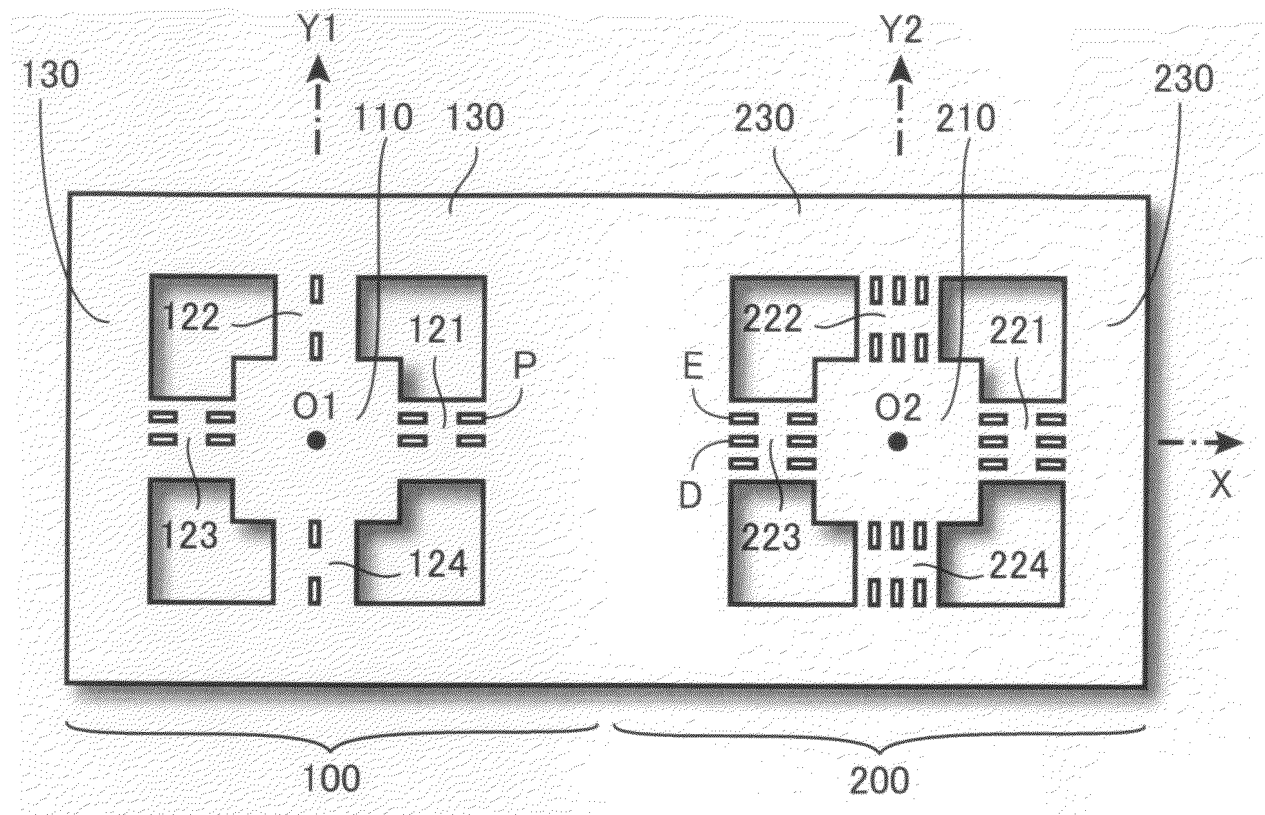
[0164]FIG. 1 is a top view of an exemplary sensor according to a first embodiment of the present invention. As shown in FIG. 1, the left half of the sensor constitutes an acceleration detecting section 100, while the right half constitutes an angular velocity detecting section 200. The major structures of the acceleration detecting section 100 are a square-columnar weight body 110 for acceleration detection, four plate-like bridge portions 121 to 124, and a pedestal 130 for acceleration detection. The pedestal 130 has a square contour arranged in such a manner as to surround the weight body 110, and the four plate-like bridge portions 121 to 124 serve as flexible connections for connecting the weight body 110 and the pedestal 130. Meanwhile, the major structures of the angular velocity detecting section 200 are a square-columnar weight body 210 for angular velocity detection, four plate-like bridge portions 221 to 224, a...

Example

Sensor According to the Second Embodiment

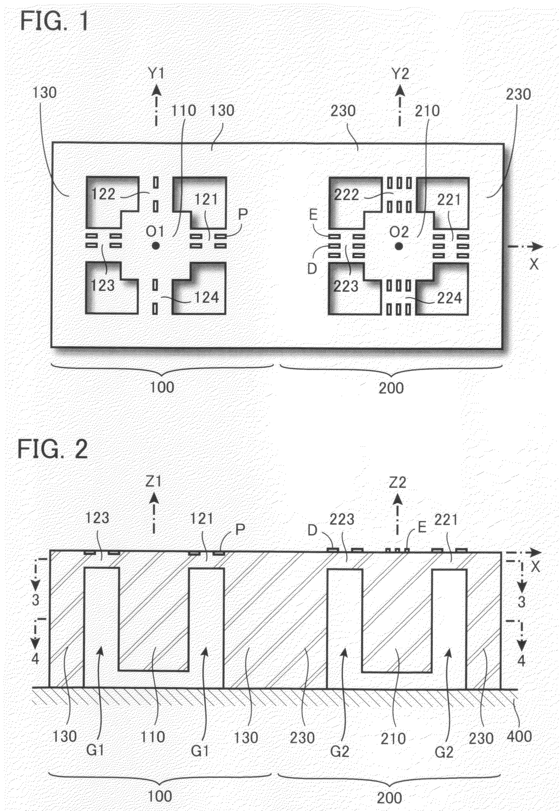
[0241]Next will be described a sensor according to a second embodiment of the present invention. The sensor according to the second embodiment can be figured out as a sensor in which the acceleration detecting section 100 and the angular velocity detecting section 200 in the sensor according to the first embodiment shown in FIG. 1 and FIG. 2 are integrated on a single major structure. As will be understood from the top view of FIG. 1 and the vertical cross-sectional view of FIG. 2, the physical structures of the acceleration detecting section 100 and the angular velocity detecting section 200 are substantially the same and equivalent to the fundamental model shown in FIG. 5 and FIG. 6. The difference between the structures is that the acceleration detecting section 100 is provided with piezoresistive elements P, while the angular velocity detecting section 200 is provided with piezoelectric elements F. In the sensor according to the second em...

Example

Sensor According to the Third Embodiment

[0278]Next will be described a sensor according to a third embodiment of the present invention. The above-described sensors have a structure in which a weight body is surrounded by a pedestal and the periphery of the weight body is supported by a flexible connection, which allows the weight body to be displaced in any direction along each coordinate axis of a three-dimensional coordinate system. Consequently, acceleration in the directions along the three-dimensional coordinate axes and angular velocity around the three-dimensional coordinate axes can be detected. The sensor according to the third embodiment to be described herein is specialized in detecting one-dimensional acceleration and angular velocity with a simpler structure.

[0279]FIG. 43 is a top view of the sensor, and FIG. 44 is a vertical cross-sectional view of the sensor. As shown in the drawings, the major structures of the sensor are a weight body 610, a flexible connection 620,...


PUM


Abstract

Static and dynamic acceleration as well as static and dynamic angular velocity are detected with a simple structure. An acceleration detecting section includes a weight body, a pedestal around the weight body, flexible plate-like bridge portions, and piezoresistive elements embedded in the upper surface of the bridge portions. An angular velocity detecting section includes a weight body, a pedestal around the weight body, flexible plate-like bridge portions, and piezoelectric elements fixed to the upper surface of the bridge portions. The pedestals are fixed to a device chassis. When the weight body is displaced by acceleration, the plate-like bridge portions are deflected, so that the acceleration is detected based on the change in the electrical resistances of the piezoresistive elements. When the weight body is displaced by a Coriolis force based on angular velocity while supplying alternating signals to the piezoelectric elements to oscillate the weight body, the plate-like bridge portions are deflected, so that the angular velocity is detected based on charge generation in the piezoelectric elements.

Description

BACKGROUND OF THE INVENTION[0001]The present invention relates to sensors for detecting acceleration and angular velocity and, in particular, to a sensor for detecting acceleration and angular velocity based on a force applied to a weight body.[0002]Industrial machinery and electronic devices are often equipped with units for detecting physical quantity such as acceleration and / or angular velocity. For this reason, many types of small-sized and high-accuracy acceleration sensors and angular velocity sensors have been developed. In particular, demand for multiaxial acceleration sensors that can detect two- or three-dimensional acceleration and multiaxial angular velocity sensors that can detect bi- or tri-axial angular velocity has been increasing. For example, recently, many digital cameras have a multiaxial acceleration sensor and / or a multiaxial angular velocity sensor incorporated therein for stabilization control. For this type of application, it is an important issue to reduce ...

Claims


Application Information

Patent Timeline
IPC IPC(8): G01P15/08G01C19/56G01P15/12G01P15/18H01L29/84H01L41/08H01L41/187
CPCG01C19/56G01P15/0922G01P15/123G01P15/18G01P2015/084
Inventor OKADA, KAZUHIRO
Owner WAKO CO LTD
Why Eureka
Try Eureka