Optical fiber guide device

Inactive Publication Date: 2005-04-26
AUTONETWORKS TECH LTD +2
View PDF19 Cites 28 Cited by
  • Summary
  • Abstract
  • Description
  • Claims
  • Application Information

AI Technical Summary

Benefits of technology

[0006]In view of the above, it is an object of the invention to provide an optical fiber guide device by means of which an optical fi

Problems solved by technology

When an abrupt bending has been applied to the optical fib

Method used


Image

  • Optical fiber guide device
  • Optical fiber guide device
  • Optical fiber guide device

Examples


Example

MODIFIED EXAMPLE 1

[0042]In place of the lid part 15 in the optical fiber guide device 5 of the above described embodiment, a lid part 15B as shown in FIG. 4 may be employed.

[0043]In particular, this lid part 15B is provided, as shown in FIGS. 4 to 6, with two pairs of extending pieces 18B which are respectively suspended from both ends of a lid body 16 having a similar structure to the one in the above described embodiment and extend so as to clamp the optical fiber cord 1 which has been received and arranged in the guide receiving part 11, from both sides thereof. Each pair of the extending pieces 18B are provided at their inner faces with rib-like stoppers 19B opposed to each other. The rib-like stoppers 19B are formed in a direction perpendicular to an axial direction of the optical fiber cord 1 received and arranged in the guide receiving part 11 and along an extending direction of the extending pieces 18B. Each of the stoppers 19B is formed in a shape of rectangular column, and...

Example

MODIFIED EXAMPLE 2

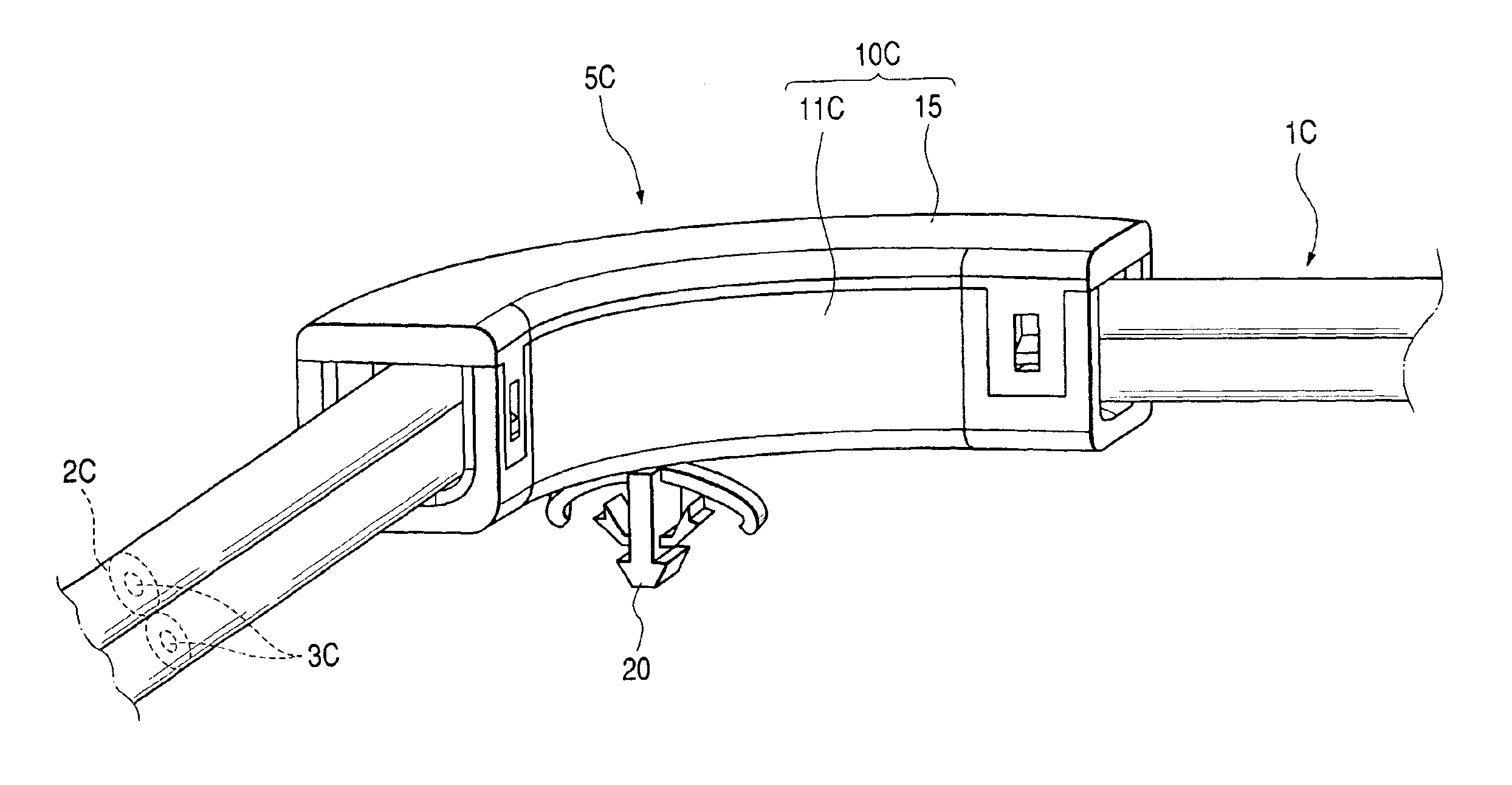
[0049]In case of guiding and holding an optical fiber cord 1C of a multi-core parallel arranged type in which a plurality of (two, in this modified example 2) optical fibers 3C are coupled in parallel by means of a coating 2C as shown in FIG. 7, in a state where the optical fiber cord 1C is bent in two dimensions in a determined plane, the guide body may be so constructed, like a guide body 10C as shown in FIG. 8, that the relevant optical fiber cord 1C may be received and held in such a posture that all the optical fibers 3C of the optical fiber cord 1C guided and held therein may be bent at the same bending radius.

[0050]In other words, an inner peripheral face of a guide receiving part 11C of the guide part 10C has a shape of an elongated hole which is longer in cross section in a vertical direction perpendicular to the determined plane, and the optical fiber cord 1C is received and held therein having the optical fibers 3C arranged in the vertical direction so t...


PUM


Abstract

An optical fiber cord 1 is guided and held in a fixed bent shape in a tubular guide body 10 which is bent in an arc. The guide body 10 is integrally provided with a mounting part 20 which can be attached to a vehicle body or the like, and by fitting this mounting part to the body or the like, installation of the optical fiber cord 1 can be conducted.

Description

BACKGROUND OF THE INVENTION[0001]1. Field of the Invention[0002]The present invention relates to an art for installing an optical fiber cord in an interior and exterior of an automobile, an apparatus, and so on.[0003]2. Description of the Related Art[0004]When an abrupt bending has been applied to the optical fiber cord, a loss of light will be increased in a bent part. For this reason, in case where the optical fiber cord is installed in an automobile or the like for example, the installation work must be conducted with a careful attention so that an abrupt bending may not be applied to the optical fiber cord, as compared with a case of installing a wire harness for electric wiring.[0005]Especially, in such a region that the optical fiber cord must be installed in a bent state, it is necessary to bear in mind that the relevant optical fiber cord should be gently bent so that an abrupt bending may not be applied thereto, and that a bent shape of the optical fiber cord should be cons...

Claims


Application Information

Patent Timeline
IPC IPC(8): G02B6/44H02G3/04B60R16/02G02B6/00F16B19/00H02G1/06H02G3/30H02G3/38H05K7/00
CPCH02G3/0487G02B6/4459H02G3/32
Inventor ASADA, KAZUHIRO
Owner AUTONETWORKS TECH LTD
Why Eureka
Try Eureka