Thermal shield and methods of construction and installation

Inactive Publication Date: 2008-07-17
FEDERAL MOGUL POWERTAIN LLC
View PDF20 Cites 28 Cited by
  • Summary
  • Abstract
  • Description
  • Claims
  • Application Information

AI Technical Summary

Benefits of technology

[0010]Accordingly, given the content of a heat shield constructed in accordance with the invention, the heat shield is lightweight, durable, effective in preventing h

Problems solved by technology

If left unchecked, the heat from the components can have adverse affects on surrounding components.
Although heat shields are well known and necessary, they typically comprise one layer of heavy, rigid material, which are becoming less effective in blocking the increased temperatures and can be difficult to form, generally requiring expensive

Method used


Image

  • Thermal shield and methods of construction and installation
  • Thermal shield and methods of construction and installation
  • Thermal shield and methods of construction and installation

Examples


Example

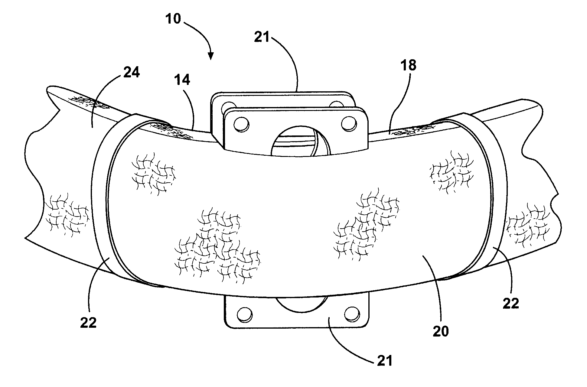
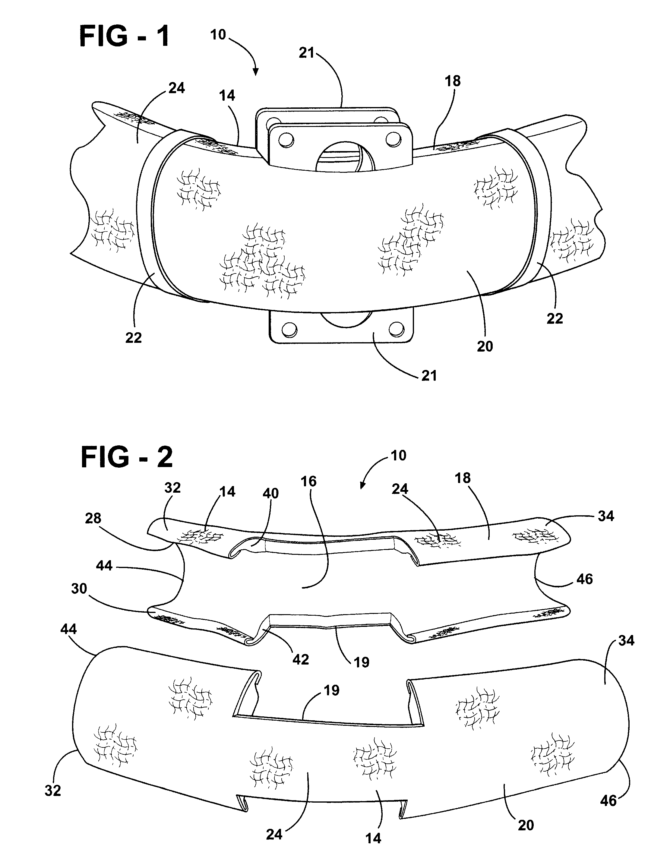
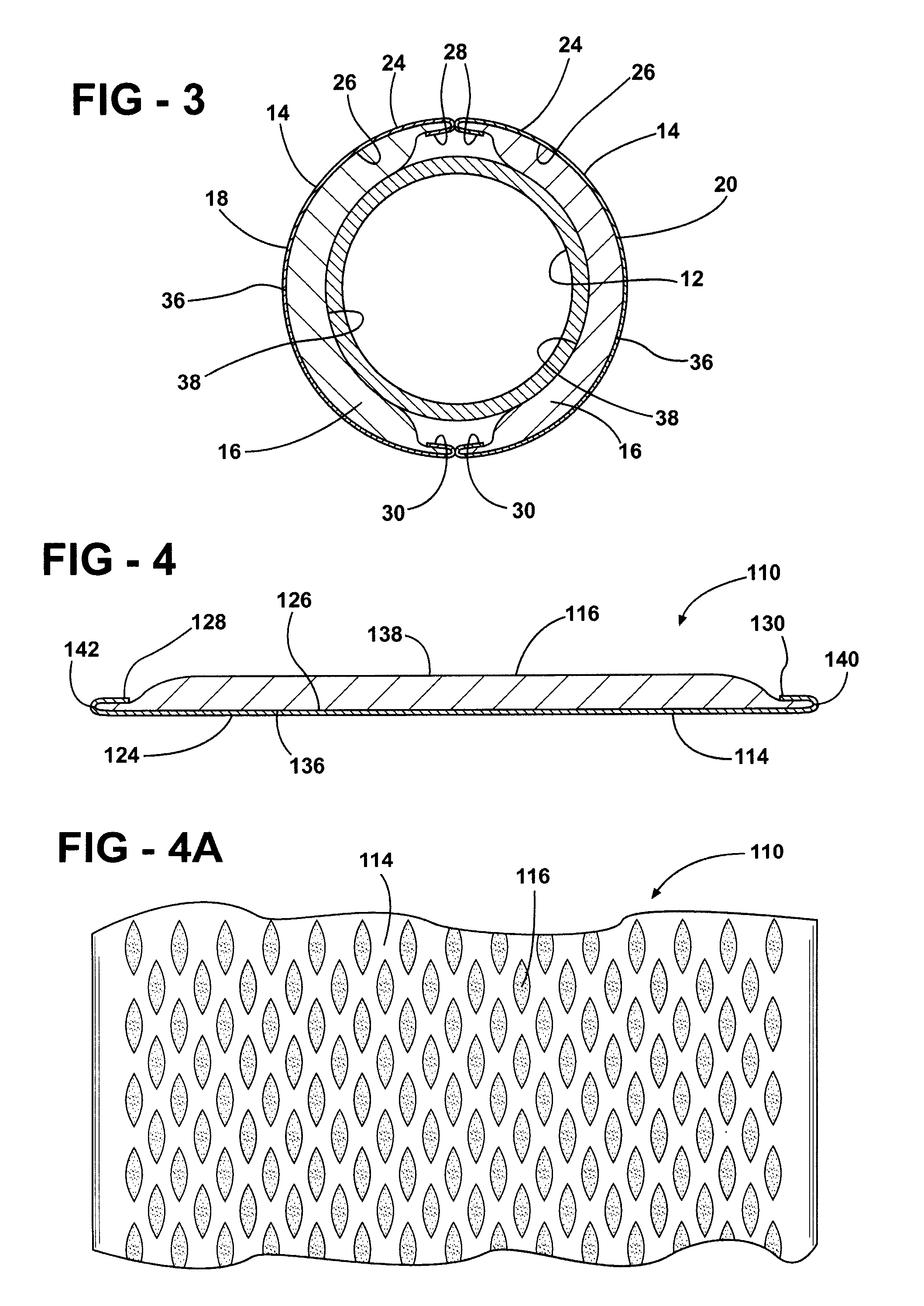
[0021]Referring in more detail to the drawings, FIGS. 1-3 show a thermal shield, referred to here after as heat shield 10, constructed according to one presently preferred embodiment of the invention. The heat shield 10 is shown formed about an exhaust pipe 12 (FIG. 3) of a vehicle, such as an automotive vehicle, motorcycle, snowmobile, or other vehicle having an exhaust system (not shown), to prevent heat from the exhaust pipe from having adverse affects on surrounding vehicle components. The heat shield 10 has a formable metallic outer layer 14 providing structure and protection to the heat shield 10, such as from debris, stones and the like, that can be kicked up from a road or ground surface. The outer layer 14 surrounds and is attached to an inner insulation layer 16 (FIGS. 2 and 3) that provides thermal insulation protection to prevent heat from radiating outwardly from the exhaust pipe 12. The heat shield 10 is light weight and economical in construction, and it can be readil...


PUM

PropertyMeasurementUnit
Widthaaaaaaaaaa
Circumferenceaaaaaaaaaa

Abstract

A wrappable heat shield for an exhaust pipe and methods of construction and installation thereor includes an outer layer of metal having opposite inner and outer faces extending between opposite sides. An inner layer of non-woven insulation is attached to the the outer layer by a crimped portion extending along one of the opposite sides of the outer layer. The inner layer has a width sufficient to extend completely about a circumference of the exhaust pipe and is arranged in continuous contact with the exhaust pipe about its circumference while the outer layer remains spaced therefrom.

Description

CROSS-REFERENCE TO RELATED APPLICATIONS[0001]This application claims the benefit of U.S. Provisional Application Ser. No. 60 / 884,551, filed Jan. 11, 2007, which is incorporated herein by reference in its entirety.BACKGROUND OF THE INVENTION[0002]1. Technical Field[0003]This invention relates generally to thermal shields, and more particularly to wrappable multilayered thermal shields.[0004]2. Related Art[0005]Vehicles and other equipment that operate via an internal combustion engine contain various components that generate relatively high temperatures. If left unchecked, the heat from the components can have adverse affects on surrounding components. For example, an automotive vehicle has an exhaust system including exhaust pipes and catalytic converters which can reach 1200° Fahrenheit (° F.) or more. As such, it is generally desirable to place a thermal barrier, often referred to simply as a heat shield, adjacent the exhaust pipes and / or catalytic converter to prevent radiant hea...

Claims


Application Information

Patent Timeline
IPC IPC(8): B21D53/88B21D51/16B60K13/04F01N13/14F01N13/08
CPCB32B1/08B32B15/14B32B15/18F01N13/148Y10T29/49398F16L59/022F16L59/024Y10T29/49879F01N2260/20F01N13/08F01N13/14
Inventor SELLIS, TIMOTHY DAVIDBURDY, JOHN EMERSONZHANG, ZHONG HUAILUDY, LINWOODRUBEL, WILLIAM T.
Owner FEDERAL MOGUL POWERTAIN LLC
Why Eureka
Try Eureka