Valve position adjustable lock mechanism

Inactive Publication Date: 2000-02-01
BADGER METER
View PDF4 Cites 31 Cited by
  • Summary
  • Abstract
  • Description
  • Claims
  • Application Information

AI Technical Summary

Benefits of technology

Another feature of the present invention is to provide a valve position adjustable lock mechanism which is easy to install, easy to adjust,

Problems solved by technology

A disadvantage of these types of stopper members is that they are time consuming to install, they are not precise and often become

Method used


Image

  • Valve position adjustable lock mechanism
  • Valve position adjustable lock mechanism
  • Valve position adjustable lock mechanism

Examples


Example

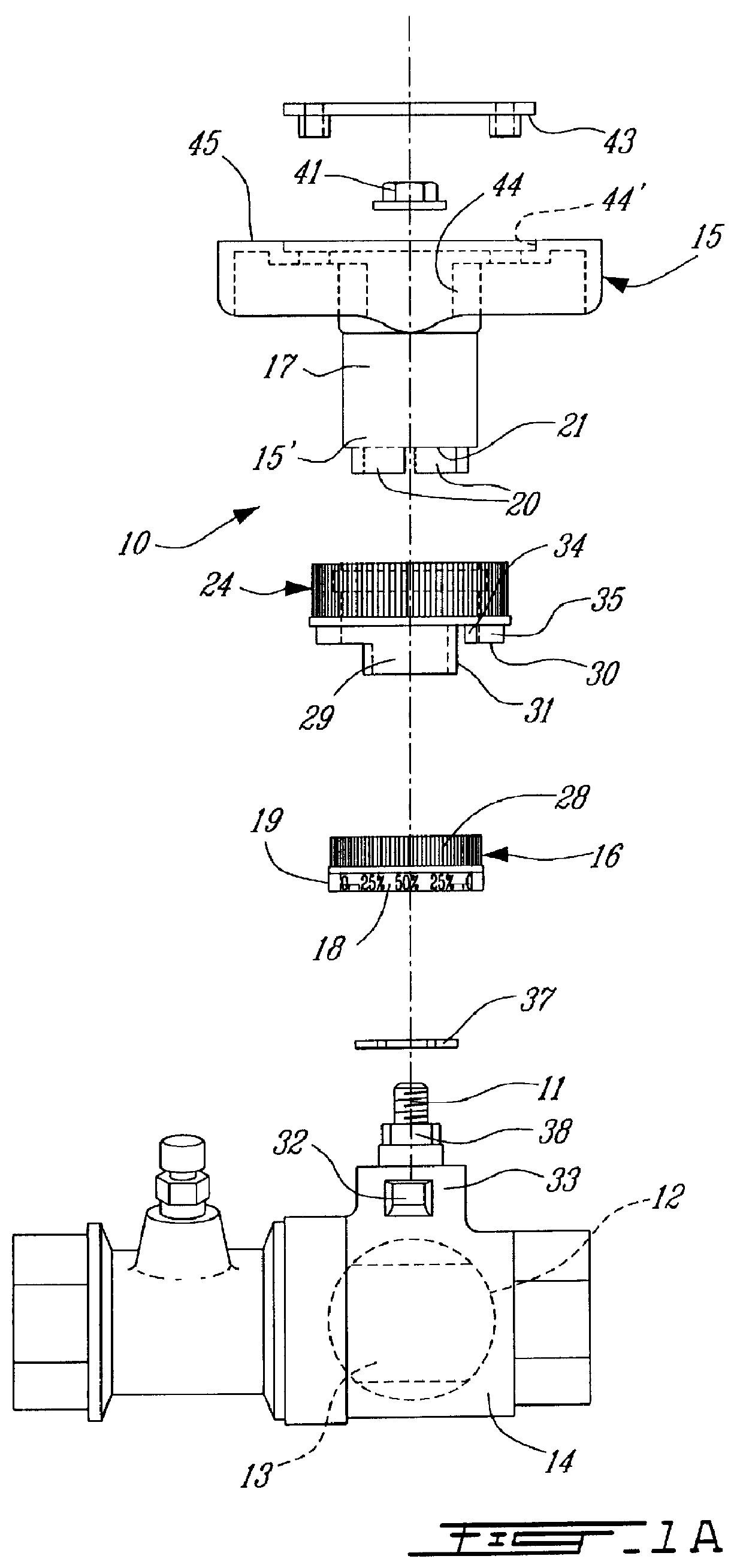
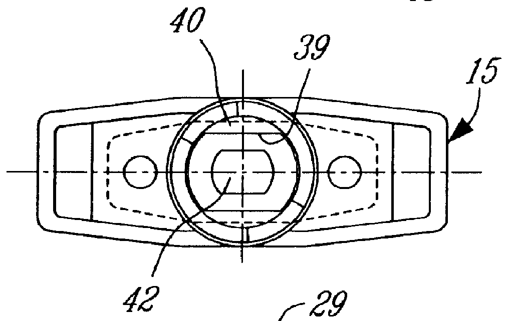
Referring now to the drawings and more particularly to FIGS. 1A to 4B, there is shown, in an exploded form, and generally at 10, the adjustable lock mechanism which is secured to the stem 11 of a ball valve element 12 mounted in a valve port 13 in a valve body 14. The adjustable lock mechanism provides for the handle 15 to be rotatable from a fully closed to a preselected open position between the fully closed and fully open position of the ball valve element 12.

As hereinshown the adjustable lock mechanism comprises an indicator ring 16 which is securable to the lower portion 15' of the lower cylindrical stem 17 of the handle 15. The indicator ring 16 is provided with position indicias 18 about a portion of its lower circumference 19 to indicate the position of the valve element from its fully open to its fully closed position. The lower portion 15' of the handle 15 has a pair of projections 20 which depend from a lower edge 21 thereof and disposed at predetermined spaced locations ...


PUM


Abstract

A valve position adjustable lock mechanism is secured to the handle which is connected to the stem of a valve element to control the position of the valve element and accordingly the size of the opening of the valve element. An indicator ring is secured to the handle and is provided with position indicias thereon to indicate the position of the valve element from a fully open to a fully closed position. An arresting projection arrests the handle at the fully open and fully closed positions. A stopper ring is disposed over the indicator ring and displaceable for engagement and disengagement therewith. The stopper ring has an abutment flange for abutment with a fixed stop element secured to the valve body. The stopper ring has an alignment window to position the abutment means at a desired location selected by the position of the alignment window relative to the position indicias on the indicator ring.

Description

The present invention relates to a valve position adjustable lock mechanism consisting of an indicator ring and a stopper ring which are engageable with each other at a predetermined position whereby to restrict the rotation of a handle connected to the stem of a valve element whereby the valve element may be disposed at a predetermined position between a fully open to a fully closed position.Known ball valves are controlled by a handle secured to a projection portion of a stem connected to the ball valve and extending exteriorly of the valve body. An abutment flange is secured to the valve handle and abuts a fixed projection which is mounted adjacent the handle portion. When the handle is turned and the flange abuts the stop element or stop post, the handle can no longer be rotated. Accordingly, if it is desired to have the ball valve displaced from a fully closed to a half open position, then it is necessary to position the handle where the ball valve is half-open and then to disc...

Claims


Application Information

Patent Timeline
IPC IPC(8): F16K35/00F16K35/02F16K37/00
CPCF16K35/022F16K37/0016Y10T137/8225Y10T137/8292Y10T137/8275
Inventor TAHA, SAMI
Owner BADGER METER
Why Eureka
Try Eureka