Print head alignment systems and methods for increasing print resolution

a print head and alignment technology, applied in the field of digital printing technology, can solve the problems of inability to accurately align the nozzles, the nozzles are typically much slower than offset printing, and the seating on the carriage may skew the alignment of the nozzles with respect, so as to facilitate the efficiency of print head alignment, improve print resolution, and reduce the effect of printing system downtim

Inactive Publication Date: 2014-06-19
CIMPRESS SCHWEIZ
View PDF6 Cites 33 Cited by
  • Summary
  • Abstract
  • Description
  • Claims
  • Application Information

AI Technical Summary

Benefits of technology

[0012]To solve the problems indicated above, various methods, systems, and tools which generally make use of an intermediary alignment adapter placed between the print head and print head carriage mounting plate of the print head carriage can facilitate efficiency in print head alignment, shorter printing system downtime due to print head alignment, and higher print resolution achievable for printed matter.
[0015]In a further embodiment, a method operates to maximize print production efficiency. The method includes printing one or more print jobs using a printing system, wherein the printing system comprises a print head carriage which carries a first set of one or more print heads, a first set of one or more alignment adapters configured to hold the one or more print heads and having a corresponding aperture through which respective nozzles of the respective print heads are exposed, the first set of alignment adapters having precision mounting features configured to engage corresponding cooperating precision mounting features of the print head carriage and which are configured to align the alignment adapter in a predetermined position relative the print head carriage, and further wherein the printing system comprises a printing apparatus configured to receive a print substrate on which an image is to be printed and which controls relative movement between the print head carriage and the print substrate to effect printing of the image onto the substrate. The method further includes the step of during printing of the one or more print jobs using the printing system, pre-aligning one or more print heads to a second set of one or more alignment adapters, the second set of alignment adapters having corresponding one or more apertures through which respective nozzles of the respective print heads are exposed, the second set of alignment adapters having first precision mounting features configured to engage corresponding cooperating second precision mounting features of the print head carriage, the first precision mounting features and the second precision mounting features configured to ensure precise alignment of the second set of alignment adapters in corresponding predetermined positions relative to the print head carriage. The method further includes the steps of halting printing production by the printing system, removing the first set of print heads and corresponding first set of alignment adapters from the print head carriage, and engaging the precision mounting features of the second set of alignment adapters with corresponding cooperating precision mounting features of the print head carriage to align the second set of alignment adapters with pre-aligned print heads mounted thereon to the print head carriage.
[0018]In still another embodiment, a method for increasing resolution of printed matter to be printed using a print head carriage comprising a plurality of print heads includes the steps of aligning a first set of one or more print heads in a first set of corresponding one or more print head sockets, the first set of print heads aligned, with a first offset, relative to a predetermined location on the print head carriage, and aligning a second set of one or more print heads in a second set of corresponding one or more print head sockets, the second, set of print heads aligned, with a second offset different than the first offset, relative to the predetermined location on the print head carriage.

Problems solved by technology

However, in its early days, inkjet printing was typically much slower than offset printing due to limitations of the hardware.
Furthermore, because inkjet printing prints a digital image, limitations on the obtainable printed resolution often made offset printing or laser printing the better choices over inkjet for applications requiring very high quality printing.
However, with respect to the edges of the print head package (e.g., the housing, cover, and mounting plate), the nozzles are not necessarily as accurately aligned.
Furthermore, when a print head is mounted onto a print head carriage, its seating on the carriage may skew the alignment of the nozzles with respect to the carriage and / or with respect to the nozzles of other print heads seated on the carriage.
On a print head carriage which carries many print heads, this can take a significant amount of time.
In addition, since the nozzle pitch on a print head is typically on the order of tens of microns, the print head alignment process can be quite tedious and time-consuming even for the skilled technician.
Due to repeated, use of the print heads by the printer, the print heads can wear out or clog over time, and therefore individual print heads on the carriage need to be replaced intermittently.
This process can take hours or even up to days of a technician's time to replace and align or re-align the print heads on the carriage.
Unless another print head carriage is available and ready to go with previously-aligned print heads, the printer becomes unavailable for use during the duration of the replacement and alignment process.
In a production environment, this may be unacceptable.

Method used


Image

  • Print head alignment systems and methods for increasing print resolution
  • Print head alignment systems and methods for increasing print resolution
  • Print head alignment systems and methods for increasing print resolution

Examples


Embodiment Construction

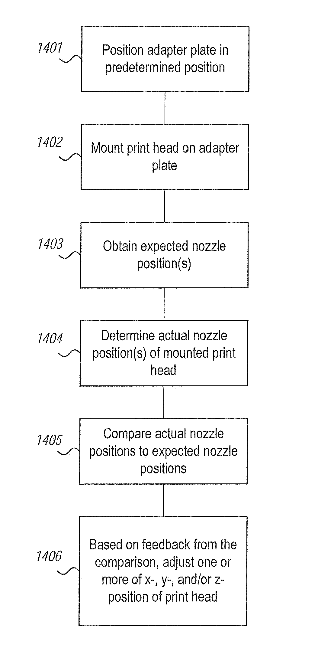
[0060]To solve the problems indicated above, offline print head alignment is performed by loading and pre-aligning individual print head(s) on an alignment adapter, and then aligning and fixing the loaded, alignment adapter to the print head carriage. The alignment adapter includes precision locating features that precisely align with precision locating features on the carriage such that the alignment adapter is placed in a precise location relative to the print head carriage every time. To align a print head to the alignment adapter, the print head is fitted into the alignment adapter as assisted by print head mounting features of the alignment adapter. The print head spatial position and / or angular rotation is adjusted, either manually and / or automatically, with respect to the alignment adapter to align the print head such that the nozzles of the print head are located in predetermined aligned positions relative to features of the alignment adapter. Once the print head is aligned ...


PUM


Abstract

Systems and methods for pre-aligning print head(s) to alignment adapter(s) to increase print resolution of printed matter, and to reduce offline time of a printing system due to print head alignment, include the use of an alignment adapter to which a print head is pre-aligned and which includes precision alignment features which precisely engage cooperating precision alignment features on the print head carriage mounting plate of the print head carriage. Print head(s) can be pre-aligned and fine-tuned to alignment adapter(s) even while the printing system is still in print production. Pre-aligned print head / alignment adapter assemblies can then be quickly mounted on the print head carriage using the cooperating precision alignment features of the adapter and print head carriage mounting plate. Duplicate sets of print head mounting sockets can include print heads aligned at different relative offsets (e.g., half a pixel) to increase the print resolution.

Description

CROSS-REFERENCE TO RELATED APPLICATIONS[0001]The present application is related to U.S. patent application entitled “System And Method For Print Head Alignment Using Alignment Adapter”, to Moreau et al, and having U.S. Application Ser. No. ______, filed concurrently herewith on Dec. 19, 2012, and U.S. patent application entitled “System And Method For Offline Print Head Alignment”, to Viet-Ngo et al., and having U.S. Application Ser. No. ______, filed concurrently herewith on Dec. 19, 2012, and U.S. patent application entitled “Print Head Pre-Alignment Systems And Methods”, to Moreau et al, and having U.S. Application Ser. No. ______, filed concurrently herewith on Dec. 19, 2012, each of which is incorporated herein by reference in its entirety.BACKGROUND OF THE INVENTION[0002]The present invention relates generally to digital printing technology, and more particularly to techniques for aligning print heads on a print head carriage of a printer.[0003]Printing technologies have advan...

Claims


Application Information

Patent Timeline
Patent Type & Authority Applications(United States)
IPC IPC(8): B41J2/045
CPCB41J2/155B41J2202/19B41J2202/20B41J25/34B41J2202/14B41J25/003B41J25/001B41J25/308B41J25/3086
Inventor MOREAU, JEAN-MICHELFEISTENAUER, HARALDNGO, HUNG VIETSTEPANEK, PATRICK
Owner CIMPRESS SCHWEIZ
Why Eureka
Try Eureka