Apparatus for suppressing fuel evaporative gas emission

a technology of evaporative gas and apparatus, which is applied in the direction of machines/engines, pumping plants, transportation and packaging, etc., can solve the problems of fuel evaporative gas not being able to be adsorbed to activated carbon in a canister, the inability to discharge to the intake passage of the internal combustion engine, and the opportunity for leak detection

Active Publication Date: 2014-06-26
MITSUBISHI MOTORS CORP
View PDF31 Cites 21 Cited by
  • Summary
  • Abstract
  • Description
  • Claims
  • Application Information

AI Technical Summary

Benefits of technology

[0019]Thus, open sticking of the tank opening/closing portion is determined based on a detection result of one pressure detection portion, thereby reducing...

Problems solved by technology

However, in a vehicle such as a plug-in hybrid vehicle that includes an internal combustion engine and also an electric motor, and travels mainly with a drive force of the electric motor, the internal combustion engine is rarely operated in order to improve fuel efficiency, and if a leak in the apparatus for suppressing fuel evaporative gas emission is to be detected in operation of the internal combustion engine, there are few opportunities for leak detection.
In such an apparatus for suppressing fuel evaporative gas emission, if failures occur such as open sticking that is sticking of the changeover valve, the sealing valve, and the purg...

Method used


Image

  • Apparatus for suppressing fuel evaporative gas emission
  • Apparatus for suppressing fuel evaporative gas emission
  • Apparatus for suppressing fuel evaporative gas emission

Examples


Embodiment Construction

[0027]Now, an embodiment of the present invention will be described with reference to the drawings.

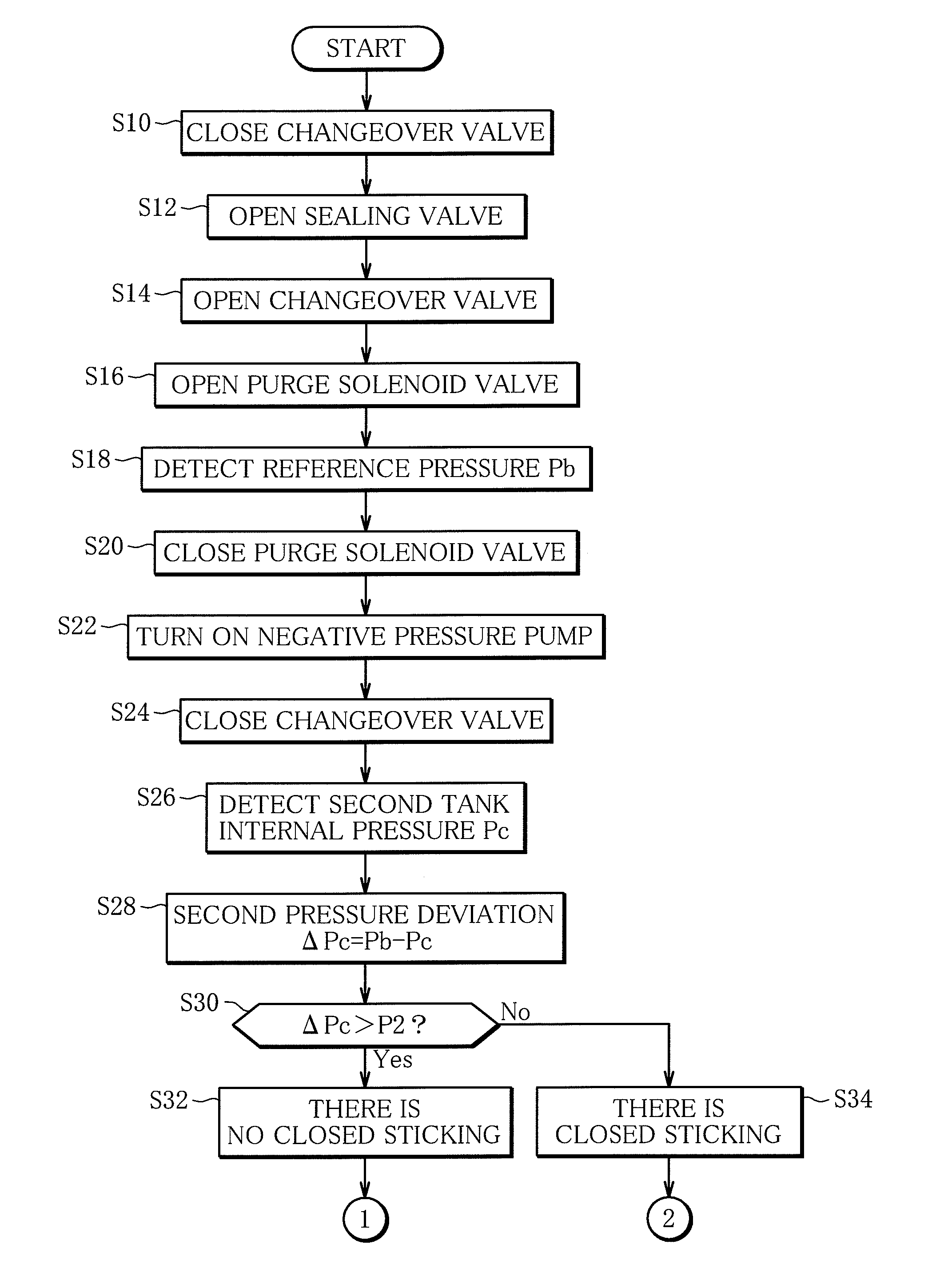
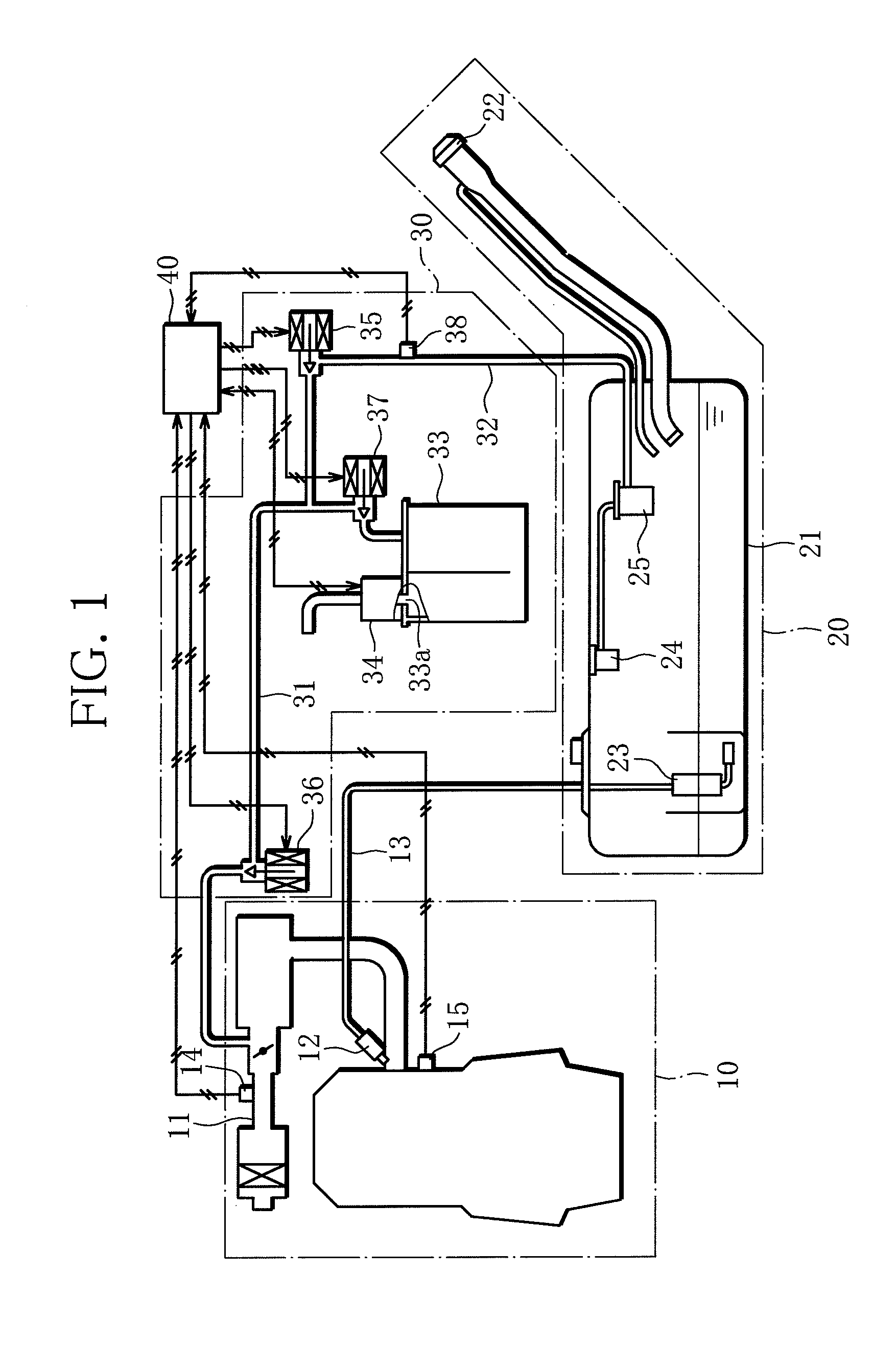
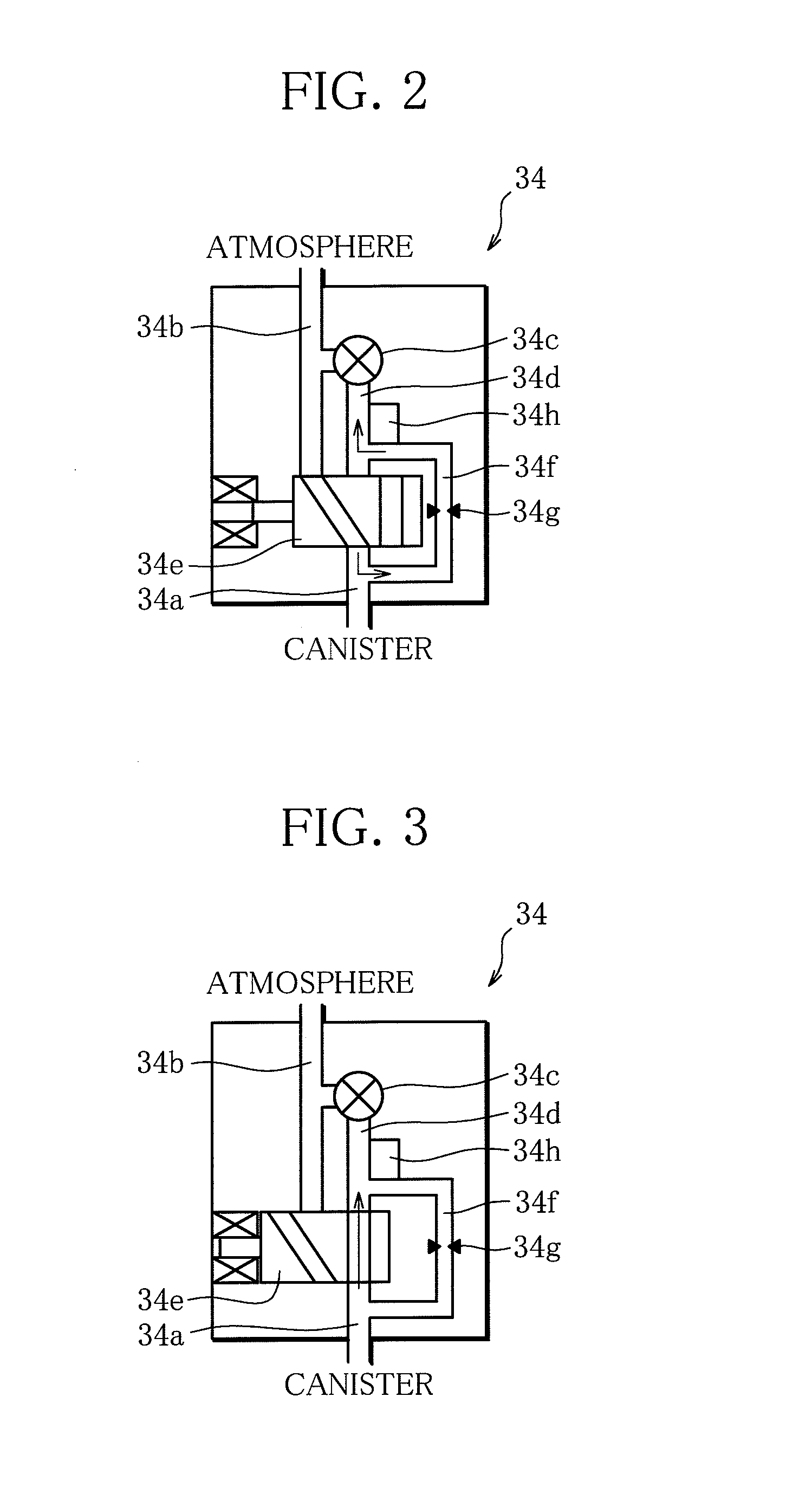
[0028]FIG. 1 is a schematic diagram of an apparatus for suppressing fuel evaporative gas emission according to the present invention. FIG. 2 shows an operation of an internal component when a changeover valve of an evaporative leak check module is not operated, and FIG. 3 shows an operation of the internal component when the changeover valve of the evaporative leak check module is operated. Arrows in FIGS. 2 and 3 show a flow direction of air when a negative pressure pump described later is operated in a shown state. The changeover valve is opened when not operated as in FIG. 2, and closed when operated as in FIG. 3. A configuration of the apparatus for suppressing fuel evaporative gas emission will be described below.

[0029]The apparatus for suppressing fuel evaporative gas emission according to the present invention is used for a hybrid vehicle that includes a traveling motor and an e...


PUM


Abstract

A purge solenoid valve is opened to introduce an atmospheric pressure into a fuel tank, the purge solenoid valve is closed to operate a negative pressure pump, and set an internal pressure of the tank to a reference pressure Pb. Then, a changeover valve is closed, and the purge solenoid valve is opened to cause a canister to communicate with an intake passage. Further, the changeover valve is opened, and the purge solenoid valve is closed. Then, a first tank internal pressure Po is detected and subtracted from the reference pressure Pb. If a calculated first pressure deviation ΔPo is larger than a first threshold ΔP1, it is determined that there is no open sticking in a sealing valve.

Description

BACKGROUND OF THE INVENTION[0001]1. Field of the Invention[0002]The present invention relates to an apparatus for suppressing fuel evaporative gas emission, and more particularly to control for detecting an abnormality of the apparatus for suppressing fuel evaporative gas emission.[0003]2. Description of the Related Art[0004]Conventionally, in order to prevent emission of a fuel evaporative gas evaporated in a fuel tank into the atmosphere, an apparatus for suppressing fuel evaporative gas emission is provided including: a canister mounted in a purge passage that provides communication between a fuel tank and an intake passage of an internal combustion engine; a changeover valve that opens or closes the canister to or from the atmosphere; a sealing valve that provides communication or closes between the fuel tank and the canister; and a purge solenoid valve that provides communication of and interrupts the purge passage. The apparatus for suppressing fuel evaporative gas emission op...

Claims


Application Information

Patent Timeline
IPC IPC(8): B60K15/035
CPCF02M25/0809B60K15/03519B60K2015/03514B60K2015/03566B60K2015/03571B60K2015/03585B60Y2200/92Y10T137/86083
Inventor MATSUNAGA, HIDEOFURUTA, KATSUHIROIKEDAYA, HISAKAZUKAMURA, HITOSHI
Owner MITSUBISHI MOTORS CORP
Why Eureka
Try Eureka