Wiring harness

a technology of wiring harnesses and wire harnesses, applied in the field of wiring harnesses, can solve the problems of easy affecting of wiring harnesses, and achieve the effects of reducing the projection of wiring harnesses, preventing the positional displacement of retrofitting members, and wide road clearan

Active Publication Date: 2015-02-05
YAZAKI CORP
View PDF17 Cites 3 Cited by
  • Summary
  • Abstract
  • Description
  • Claims
  • Application Information

AI Technical Summary

Benefits of technology

[0008]The invention has been made in view of these situations, and an object thereof is to provide a wiring harness which can realize a reduction in its height or projection towards the road surface.
[0016]According to the first aspect of the invention, since the non-identifying portion is provided on the outer surface of the conduit member which makes up the wiring harness, the retrofit member being attached to the non-identifying portion, the wiring harness is made small in size, and the wiring harness can be laid out so as to ensure a wide road clearance relative to the ground, for example. Consequently, according to the invention, there is provided an advantage that it is possible to realize a reduction in projection of the wiring harness when it is laid out.
[0017]According to the second aspect of the invention, in addition to the advantage provided by the first aspect of the invention, there is provided the following advantage. Namely, an advantage is provided that the position of the retrofit member can be restricted by the level difference produced between the identifying portion and the non-identifying portion. By doing so, not only a positional displacement of the retrofit member is prevented, but also the position of the retrofit member is facilitated. Further, when the retrofit member is able to move, the moving range of the retrofit member can be restricted. Thus, there is also provided an advantage that an improvement in workability can be realized.
[0018]According to the third aspect of the invention, there is provided an advantage that it becomes possible to provide the preferred identifying portion and retrofit member.

Problems solved by technology

Thus, when the wiring harness is laid out on the underside of the body floor with the clamps, the wiring harness so laid out interrupts an attempt to secure a wide road clearance between the road surface and itself, resulting in a problem that the wiring harness is easily affected by small stones driven up thereagainst by the vehicle.

Method used


Image

  • Wiring harness
  • Wiring harness
  • Wiring harness

Examples


embodiment

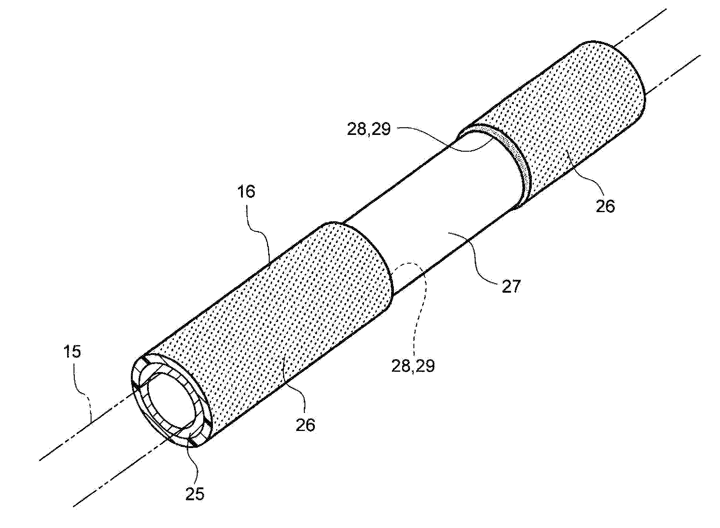
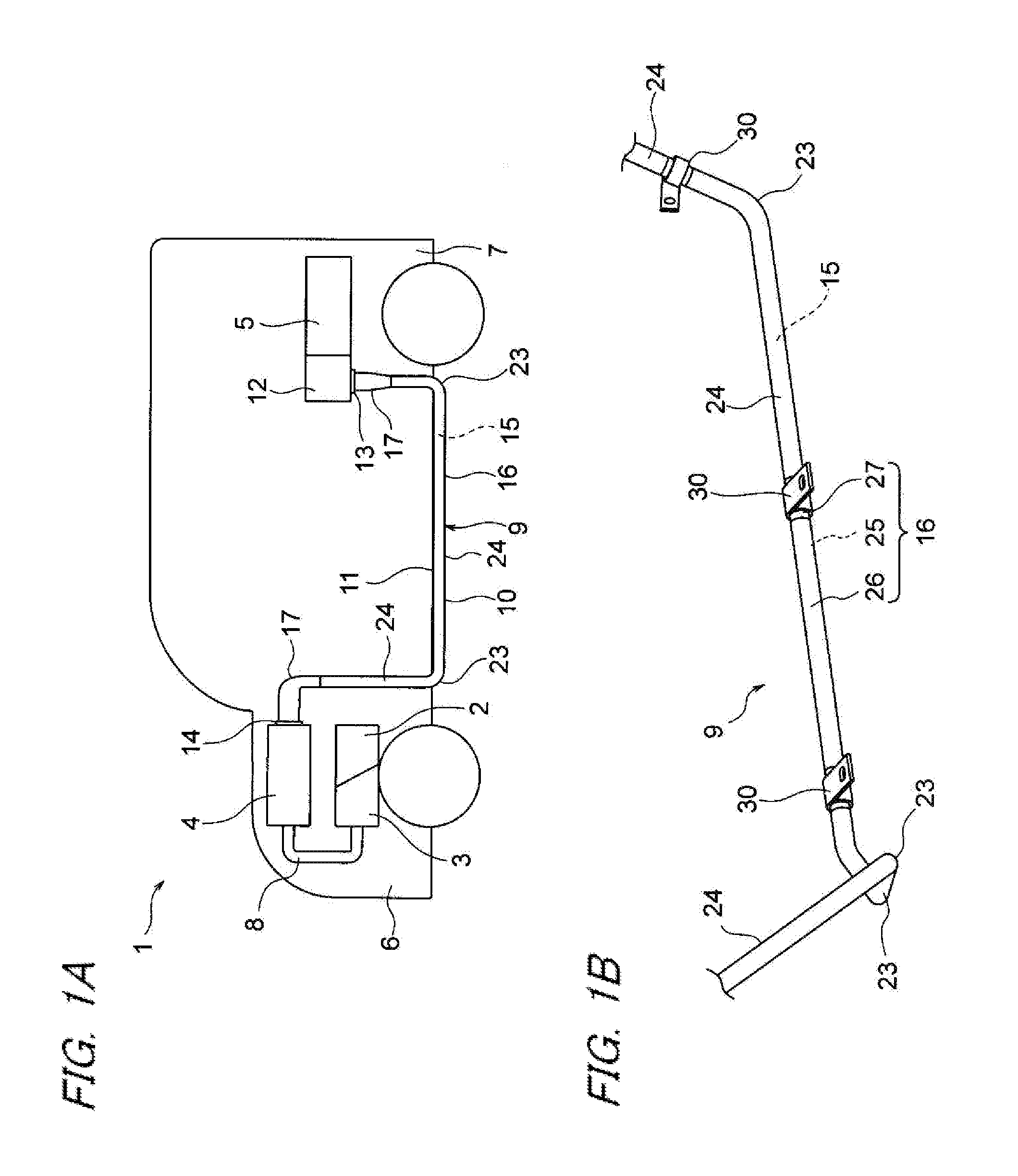
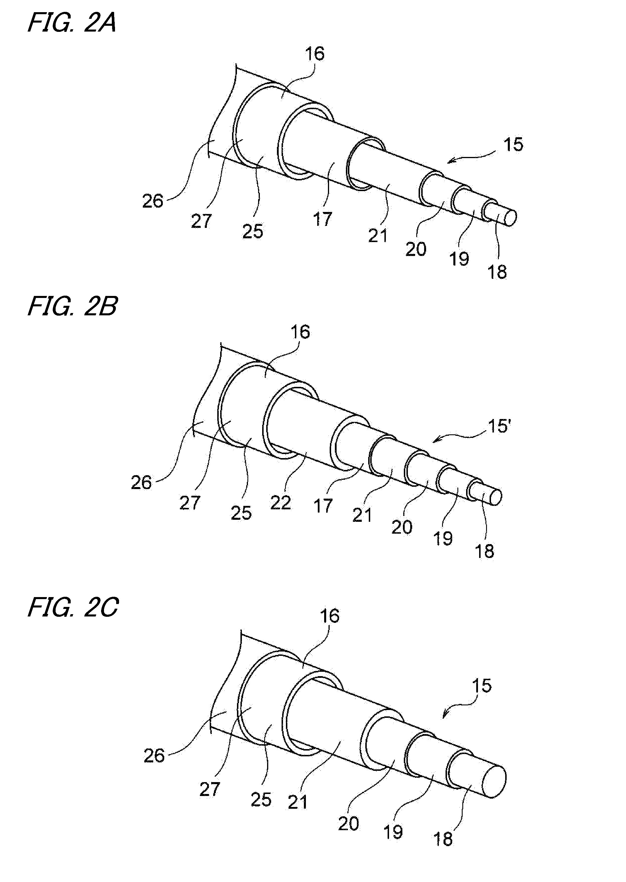
[0025]Hereinafter, an embodiment will be described by reference to the drawings. FIGS. 1A and 1B show a wiring harness of an embodiment of the invention, of which FIG. 1A shows a layout of the wiring harness and FIG. 1B shows a way in which clamps are attached to a conduit member. Additionally, FIGS. 2A to 2C show configurations of conductor lines of the wiring harness, FIG. 3 is a perspective view of an identifying portion and a non-identifying portion which are provided on an external surface of a conduit member, FIG. 4 is a perspective view showing a state in which a clamp is retrofitted to the non-identifying portion, and FIG. 5A is a side view of the wiring harness, and FIG. 5B is a partial enlarged view of FIG. 5A.

[0026]In this embodiment, the invention will be described as being applied to a wiring harness which is laid out on a hybrid vehicle (or to a wiring harness which is laid out on an electric vehicle or a general vehicle with an internal combustion engine).

[0027]In FIG...


PUM


Abstract

A wiring harness includes a conduit member which accommodates therein one or a plurality of conductor lines, and an identifying portion colored in a predetermined color and given a predetermined thickness and a non-identifying portion defined as a portion where the identifying portion is not provided circumferentially, the identifying portion and the non-identifying portion being provided on an outer surface of the conduit member. A retrofit member is attached to the non-identifying portion.

Description

CROSS REFERENCE TO RELATED APPLICATIONS[0001]This application is a continuation of PCT application No. PCT / JP2013 / 061702, which was filed on Apr. 16, 2013 based on Japanese Patent Application (No. 2012-093519) filed on Apr. 17, 2012, the contents of which are incorporated herein by reference.BACKGROUND OF THE INVENTION[0002]1. Field of the Invention[0003]The present invention relates to a wiring harness including a conduit member which accommodates a conductor line.[0004]2. Description of the Related Art[0005]A wiring harness described in JP-A-2004-224156 below includes three high tension electric wires and three metallic conduit members (metallic pipes) which accommodate individually the three high tension electric wires for protection. The high tension electric wires are provided to connect a motor mounted in a front portion of a vehicle and an inverter mounted in an intermediate or rear portion of the vehicle.[0006]The wiring harness is laid to extend along an underside of a body...

Claims


Application Information

Patent Timeline
Patent Type & Authority Applications(United States)
IPC IPC(8): B60R16/02H02G3/04
CPCH02G3/0406B60R16/0215H02G3/0481H02G3/32H02G2200/20
Inventor YOSHIDA, HIROYUKIADACHI, HIDEOMI
Owner YAZAKI CORP
Why Eureka
Try Eureka