

Panel lifter
a panel lifter and panel technology, applied in the field of panel lifters, can solve the problems of difficult lifting and manoeuvring of large and heavy drywall panels, panel lifters, etc., and achieve the effect of easy adjustment and disassembly of the panel lifter and easy sliding underneath
- Summary
- Abstract
- Description
- Claims
- Application Information
AI Technical Summary
Benefits of technology
Problems solved by technology
Method used
Image

Examples
Embodiment Construction
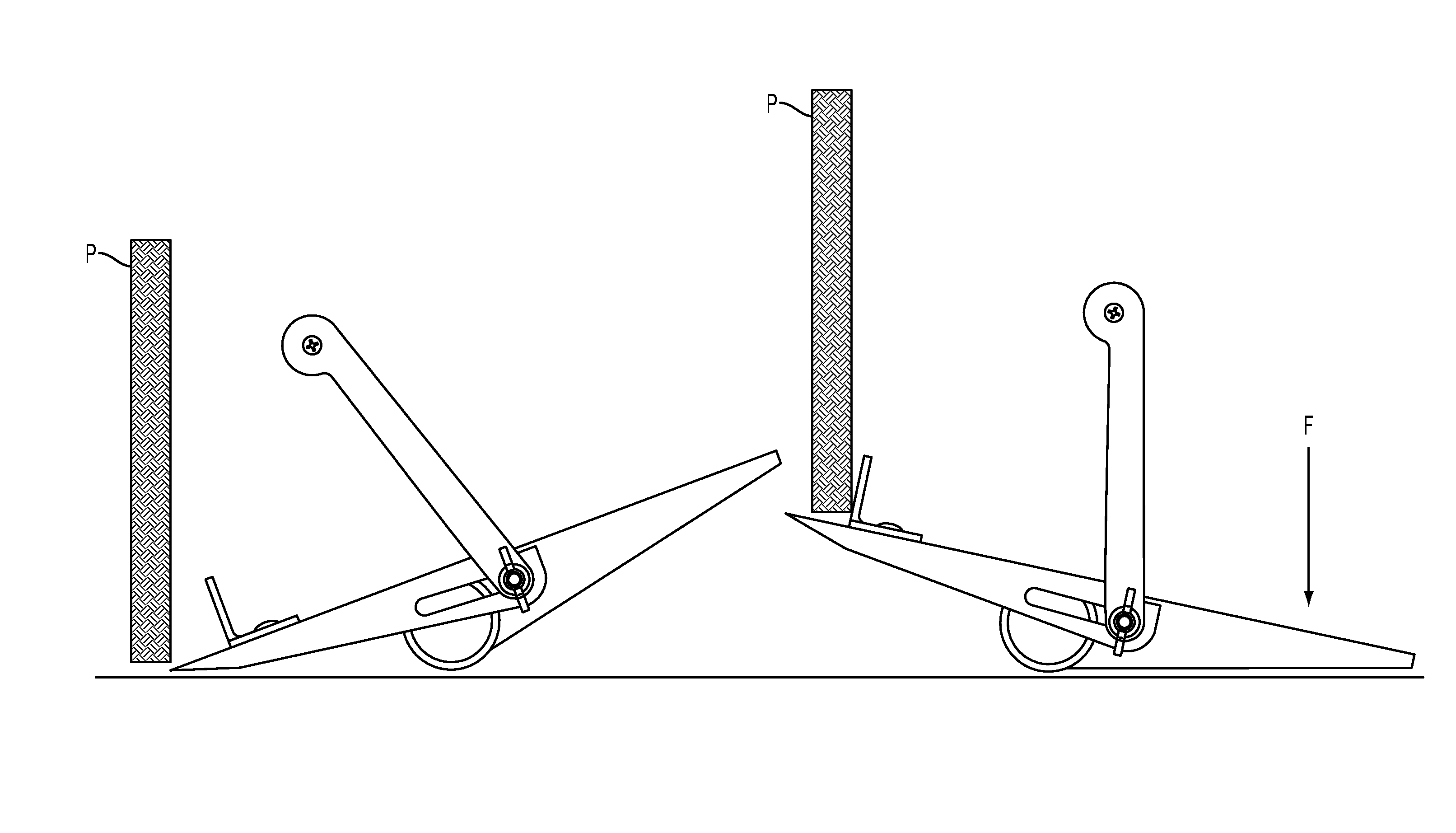
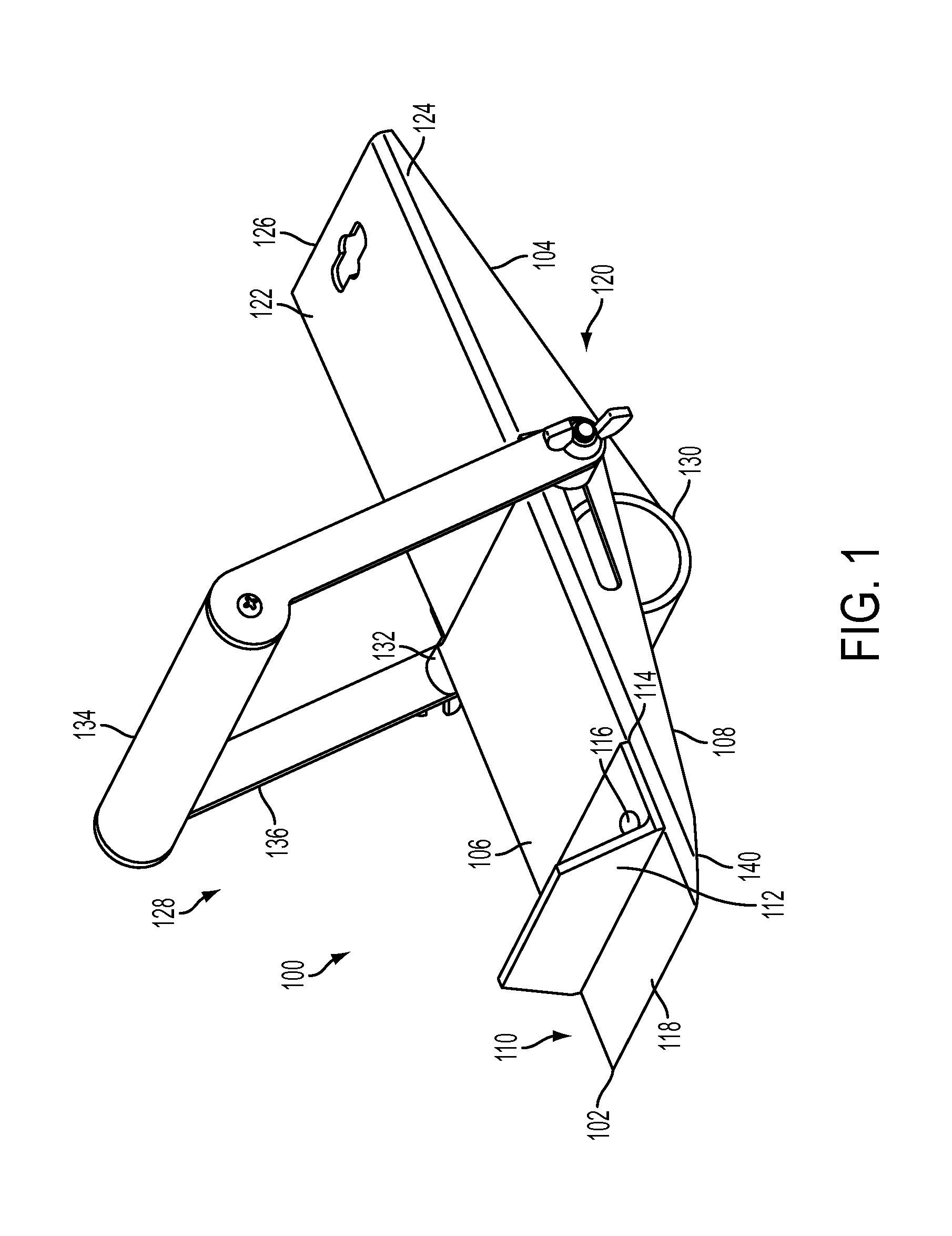
[0021]FIG. 1 shows a perspective view of a panel lifter 100. The panel lifter 10 may be used in construction and DIY where various panels are required to be lifted. For example, drywall (also known as plasterboard) is manufactured in panels which are fixed to existing interior walls or an interior timber frame. In some circumstances the panels have to be lifted and manoeuvred during fitting. Typically the panels have a generally flat shape and a thin edge (e.g. some drywall panels have the dimensions 2400 mm×1200 mm×12.5 mm). The panel lifter 10 is configured to lift drywall panels, but can be used with other panel type materials.
[0022]The panel lifter 100 comprises a first arm 102. The first arm 102 has a flat top surface 106 and two side wings 108. The first arm 102 is a generally a flat sheet and a portion thereof is folded down to form the side wings 108. The first arm 102 is a hollow wedge shape with the wedge tapering towards an end portion 118 of the first arm. The wedge is t...
PUM
 Abstract
Description
Claims
Application Information