Composite support system for a fill media cooling tower

a technology of fill media and support system, which is applied in the direction of girders, separation processes, lighting and heating apparatus, etc., can solve the problems of excessive stress on pan sections, prior art support structures that do not appreciate the need to vary height, and little thought given to the proper placement of various components that set down and position prior art support structures

Inactive Publication Date: 2007-10-09
PRATT STANLEY P
View PDF14 Cites 6 Cited by
  • Summary
  • Abstract
  • Description
  • Claims
  • Application Information

AI Technical Summary

Benefits of technology

[0010]Included herein is a support base for a crossflow cooling tower having a bundled fill pack arrangement used as the media for the heat exchange system. The cooling tower, or heat transfer device, comprises a plurality of heat exchanging plates positioned to form the fill media, a moisture collection area positioned under the heat exchanging plates, and a composite base supporting the heat exchanging plates and positioned substantially within the moisture collection area. The base in...

Problems solved by technology

Most of these prior art patents have overlooked the basic support structure used in connection with a bottom supported fill media in a cross flow cooling tower.
Additionally, little thought has been given to the proper location of the various components that set down and position the prior art support structures.
The prior art structures are normally positioned on the cold water basins often time putting excessive stress on the pan sections due to the weight of the complete fill assembly not being equally distributed across the cold water basin pan sections.
The prior art support structures fail to appreciate a need to vary the height of t...

Method used


Image

  • Composite support system for a fill media cooling tower
  • Composite support system for a fill media cooling tower
  • Composite support system for a fill media cooling tower

Examples


Embodiment Construction

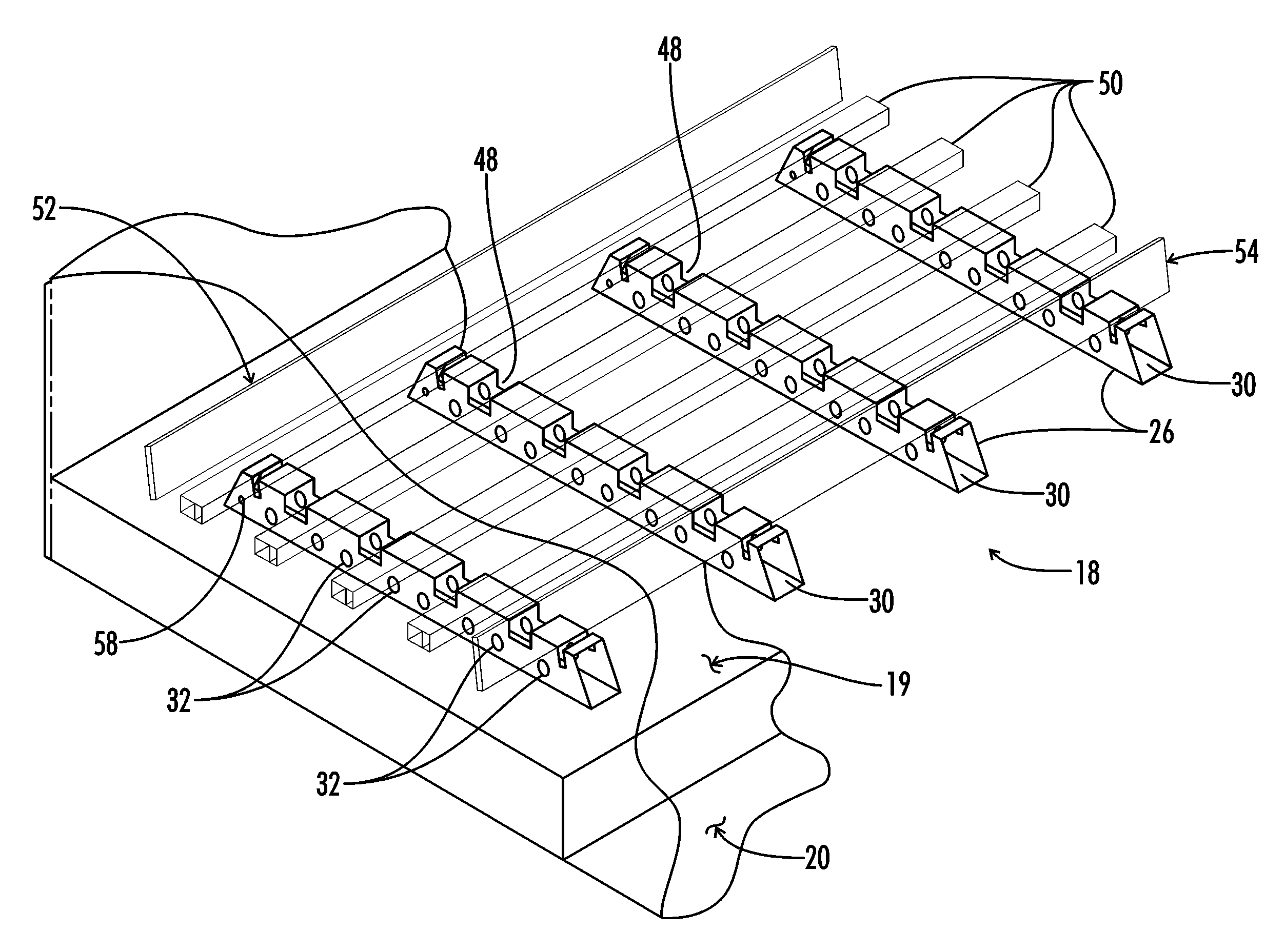
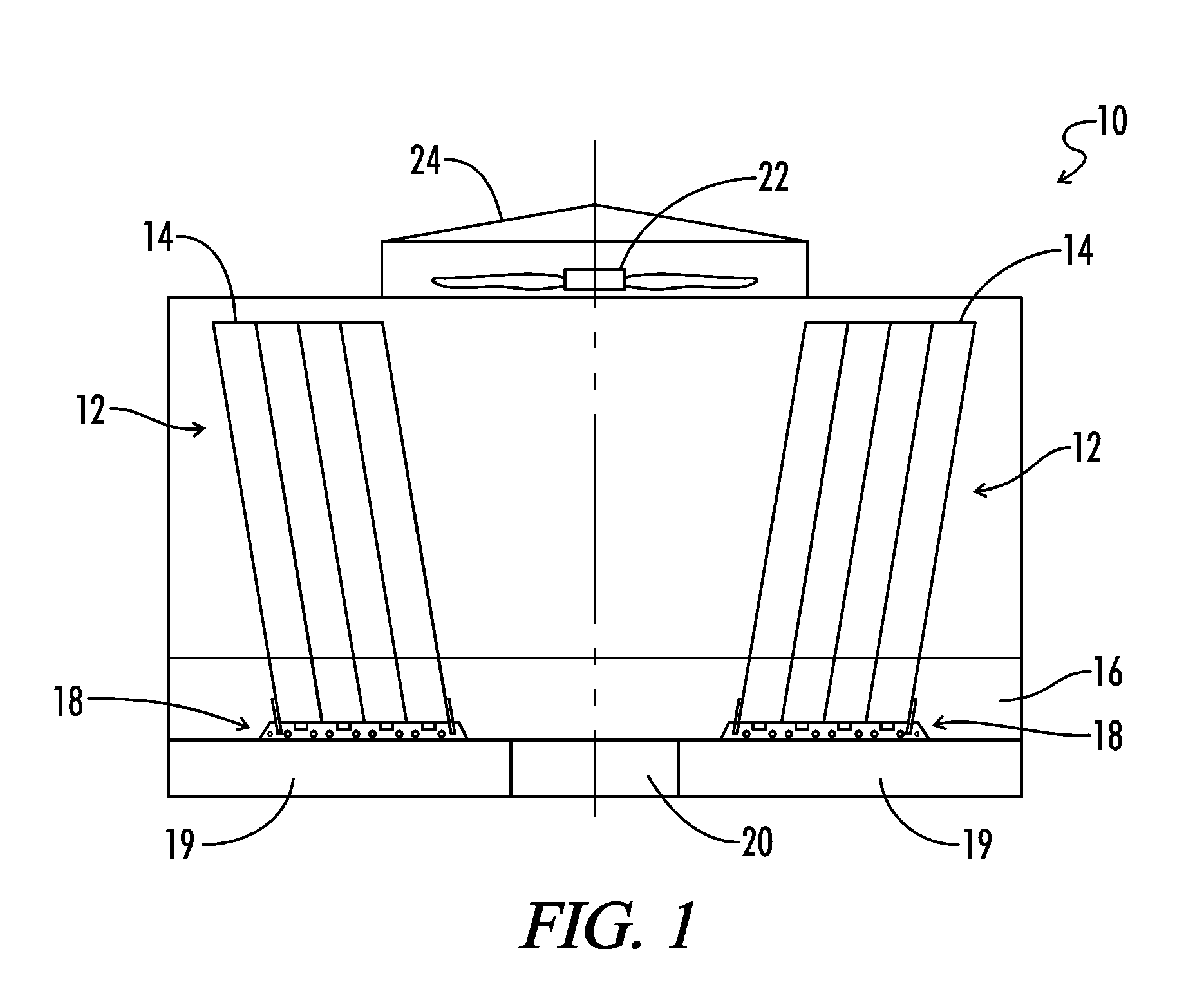
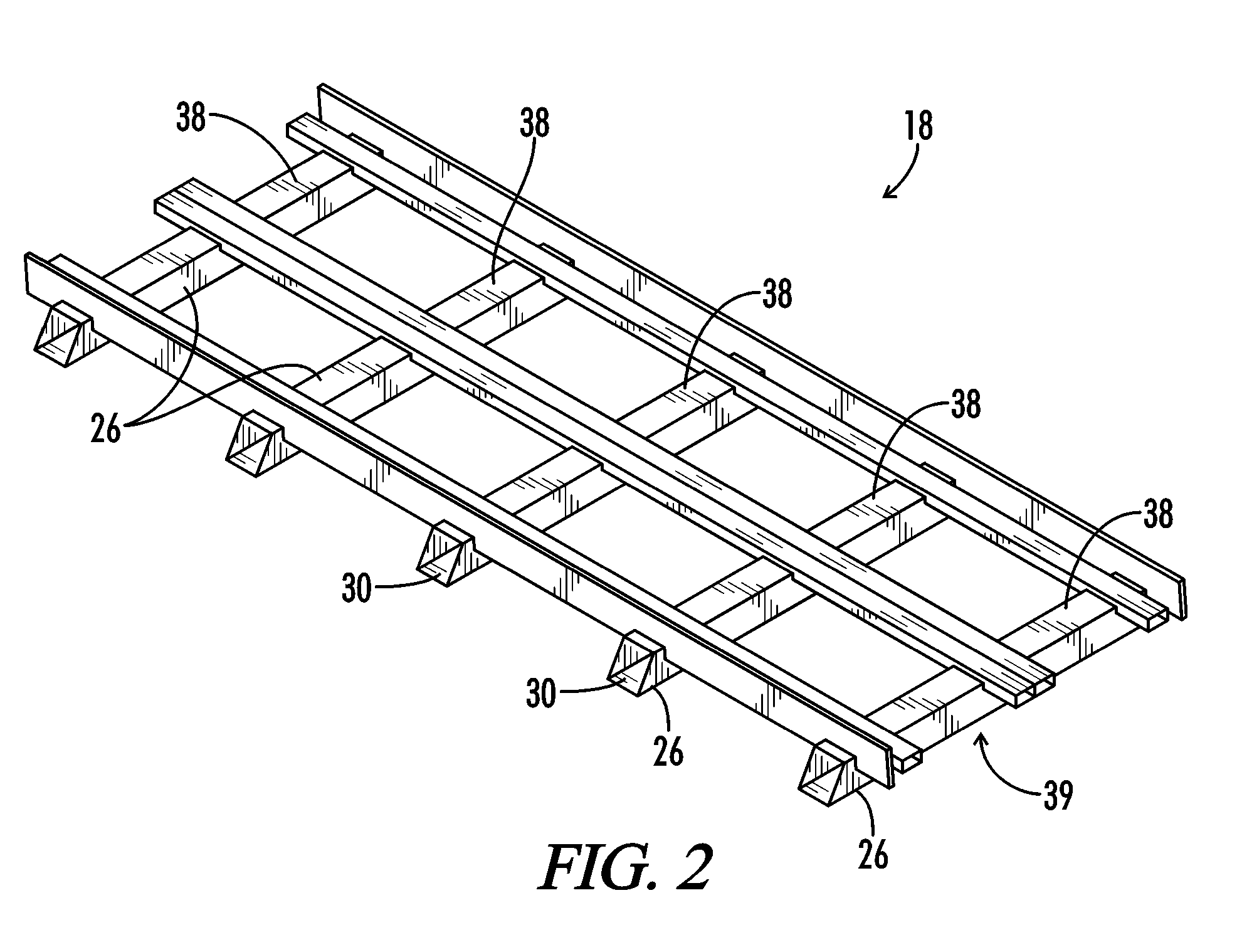
[0031]Referring generally now to FIGS. 1-6 a cooling tower is generally shown and designated by the numeral 10. The cooling tower 10, which can also be described as an evaporative heat exchanging device 10, is normally used in conjunction with an air processing system (not shown). The cooling tower 10 comprises a heat exchange system 12, which can be described as fill media 12. The fill media 12 comprises a plurality of heat exchanging plates 14 proximately positioned to form the fill media 12. A moisture collection area 16, which can be described as a cold water basin 16, is positioned under the heat exchanging plates 14 that form the fill media 12. The cold water basin 16 collects the moisture, or water, that has been cooled in the cooling tower for its subsequent use in air handling or other industrial processes.

[0032]The cooling tower 10 can further include a lower section 20, which can also be described as a subsection 20, in which the water flows for subsequent use in air or i...


PUM

PropertyMeasurementUnit
Lengthaaaaaaaaaa
Flow rateaaaaaaaaaa

Abstract

A base for a cooling tower having a fill media heat exchange system. The cooling tower, or heat transfer device, includes a plurality of heat exchanging plates positioned to form the fill media, a moisture collection area positioned under the heat exchanging plates, and a composite base supporting the heat exchanging plates and positioned substantially within the moisture collection area. The base includes a plurality of elongated supports, wherein each support includes a length, an aperture, and a plurality of openings. The aperture traverses the supports substantially parallel to the length while the openings traverse the supports substantially perpendicular to the length. The combination of the aperture and openings allows the flow of moisture and water within the moisture collection area to flow in at least two substantially perpendicular directions within the moisture collection area.

Description

CROSS-REFERENCES TO RELATED APPLICATIONS[0001]This application is a Non-Provisional Utility application which claims benefit of co-pending U.S. Patent Application Ser. No. 60 / 591,812 filed Jul. 28, 2004, entitled “Composite Support System For A Fill Media Cooling Tower” which is hereby incorporated by reference in its entirety.[0002]A portion of the disclosure of this patent document contains material that is subject to copyright protection. The copyright owner has no objection to the facsimile reproduction by anyone of the patent document or the patent disclosure, as it appears in the U.S. Patent and Trademark Office patent file or records, but otherwise reserves all copyright rights whatsoever.[0003]All patents and publications described herein are hereby incorporated by reference in their entireties.BACKGROUND OF THE INVENTION[0004]The present invention relates generally to air processing equipment used in residential, commercial, and industrial settings. The present invention re...

Claims


Application Information

Patent Timeline
IPC IPC(8): B01F3/04
CPCF28F25/082Y10S261/11
Inventor PRATT, STANLEY P.
Owner PRATT STANLEY P
Why Eureka
Try Eureka