Ventilation device for the rear region of a motor vehicle

Inactive Publication Date: 2006-11-16
SIEMENS AG
View PDF10 Cites 7 Cited by
  • Summary
  • Abstract
  • Description
  • Claims
  • Application Information

AI Technical Summary

Benefits of technology

[0009] In a preferred embodiment of the invention, a tubular air supply element is arranged in the tunnel console, which air supply element, at an end facing the rear passengers, is connected to the air outlet element or is formed integrally therewith. This air supply element is in turn situated in an outer tube, which is likewise arranged in the tunnel console and conducts air, and is mounted in said outer tube in a longitudinally displaceable manner. In this case, th

Problems solved by technology

The disadvantage caused by the air guide close to the floor and outflow of air

Method used


Image

  • Ventilation device for the rear region of a motor vehicle
  • Ventilation device for the rear region of a motor vehicle
  • Ventilation device for the rear region of a motor vehicle

Examples


Embodiment Construction

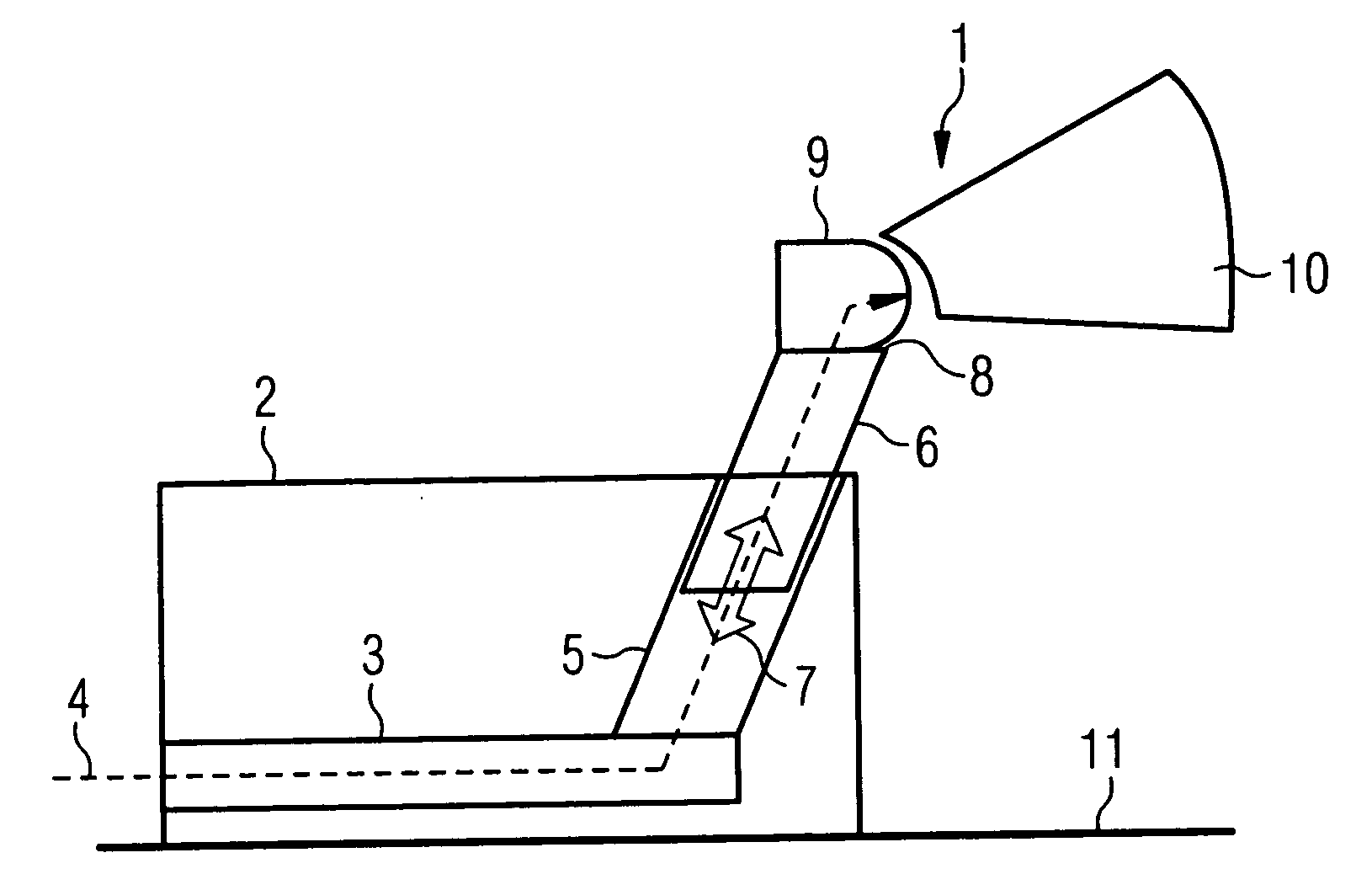
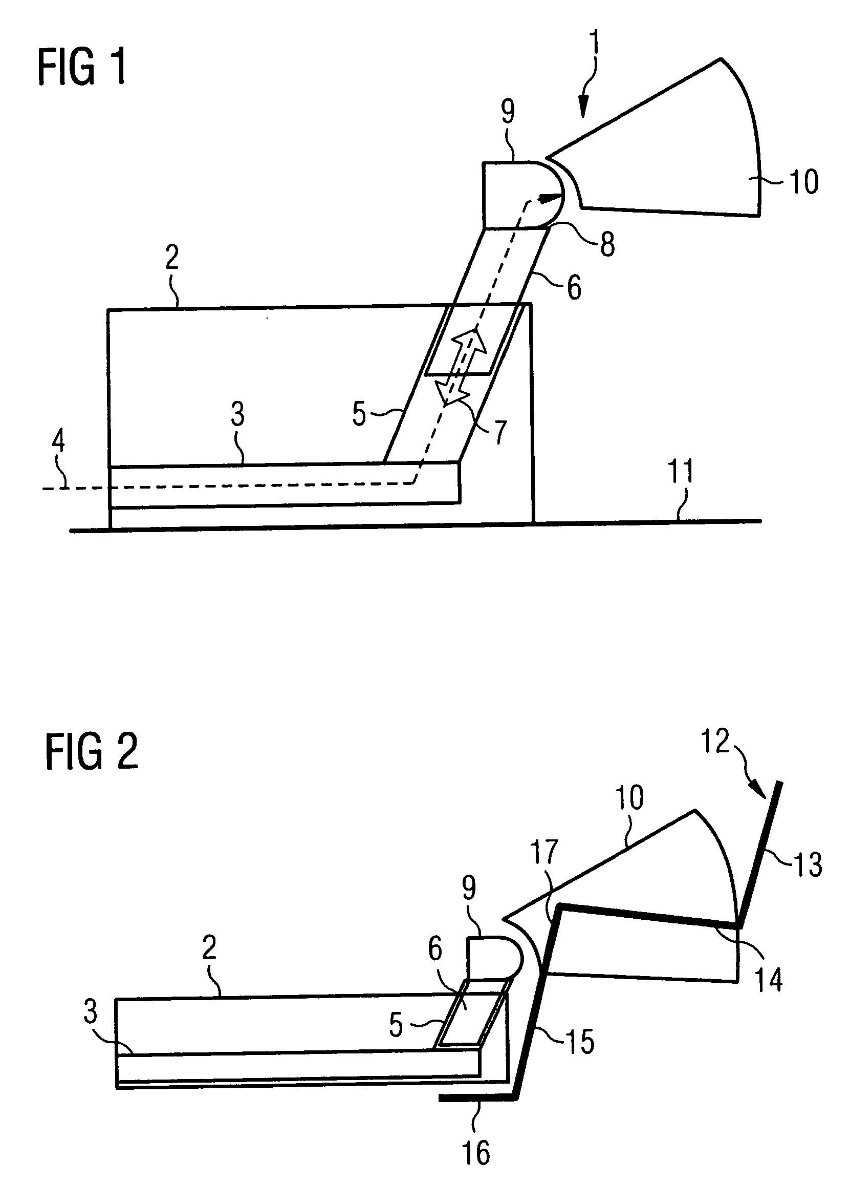
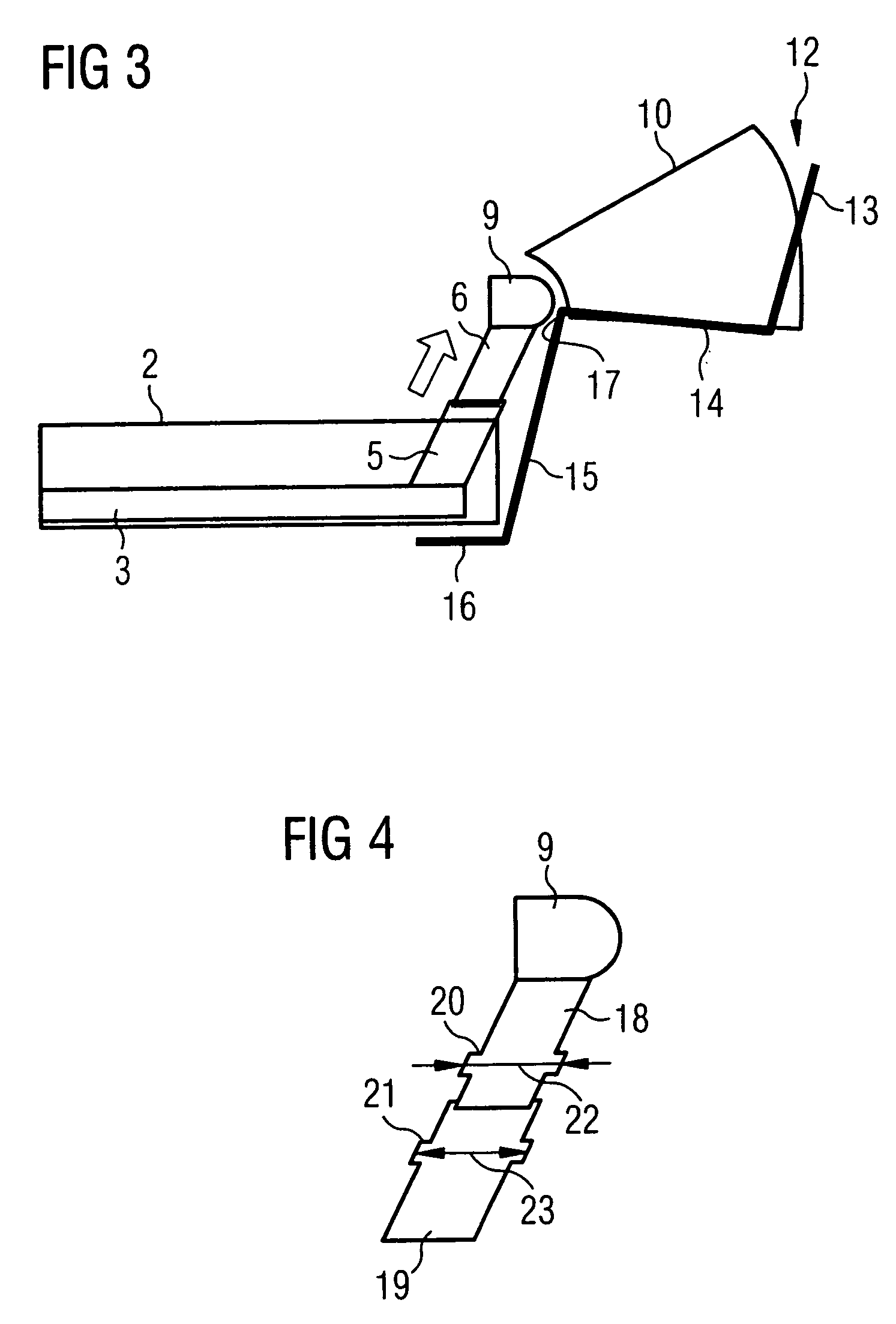
[0019]FIG. 1 shows a rear region 1 which belongs to the passenger compartment of a motor vehicle and in which a tunnel console 2 ends. An air pipe 3 through which air 4 is conveyed into the vicinity of the rear region 1 runs in the interior of the tunnel console 2. An outer tube 5 is connected to the air pipe 3. A tubular air supply element 6 is mounted displaceably in the direction 7 of its longitudinal extent in the outer tube 5. An air outlet element 9 in the form of an outlet nozzle through which the air 4 flows out in the direction of the rear region 1 is fitted at the upper end 8 of the air supply element 8. Accordingly, a longitudinal displacement of the air supply element 6 in the direction 7 leads to a vertical adjustment of the air outlet element 9 relative to the floor 11 of the rear region 1 and therefore of the passenger compartment. The overall arrangement of air pipe 3, outer tube 5 and air supply element 6 therefore forms an air guide with which the air is guided as ...


PUM


Abstract

The invention relates to a ventilation device for a motor vehicle with an air guide, in the interior of which air is conveyed into the rear region of the passenger compartment of the motor vehicle, and with an air outlet element through which the air flows out into the rear region of the passenger compartment. According to the invention, the air outlet element can be adjusted in its height relative to the floor of the passenger compartment.

Description

CLAIM FOR PRIORITY [0001] This application claims the benfit of priority to German Application No. 10 2005 017 332.2, filed in the German language on Apr. 14, 2005, the contents of which are hereby incorporated by reference. TEHCNICAL FIELD OF THE INVENTION [0002] The invention relates to a ventilation device for a motor vehicle with an air guide, in the interior of which air is conveyed into the rear region of the passenger compartment of the motor vehicle, and with an air outlet element through which the air flows out into the rear region of the passenger compartment. BACKGROUND OF THE INVENTION [0003] Ventilation outlets in motor vehicles are arranged, in each case in a fixed position, both in the region of the dashboard and in the rear region, i.e. in the region of the seats which are situated behind the driver's seat and front passenger seat. The outlet plane of the air is therefore defined in relation to the height of said outlet plane in the vehicle. Only the outlet angle can...

Claims


Application Information

Patent Timeline
IPC IPC(8): B60H1/00B60H1/34B60H1/26
CPCB60H1/00564B60H1/247B60H1/244B60H1/246
Inventor HECK, THOMAS
Owner SIEMENS AG
Why Eureka
Try Eureka