Method And Apparatus For Shielding A Linear Accelerator And A Magnetic Resonance Imaging Device From Each Other

a linear accelerator and magnetic resonance imaging technology, applied in the field of combined radiotherapy and magnetic resonance imaging, can solve the problems of signal corruption or even damage to the mri electronics, interference with the radiofrequency transmitter, and the extremely sensitive rf frequency transmit and (especially) receive coil employed

Active Publication Date: 2015-03-05
VIEWRAY TECH
View PDF6 Cites 36 Cited by
  • Summary
  • Abstract
  • Description
  • Claims
  • Application Information

AI Technical Summary

Benefits of technology

The patent text is about a device called a shield that can be used during MRI and radiation therapy to protect the patient from the MRI machine's magnetic field that may affect the effectiveness of the radiation therapy. The shield can be positioned to prevent the magnetic field from interfering with the therapy beams. This can be done using a dummy shield or by using shims to correct any distortions in the magnetic field. Overall, this device helps ensure safe and effective treatment for patients.

Problems solved by technology

However, there are two major conflicts between the linac and MRI unit that should be overcome for these technologies to work together in a clinically acceptable way.
The first problem is that the MRI unit's magnetic field accelerates charged particles in the linac by the Lorentz force on charged particles in a magnetic field determined by the equation F=q (v×B), where F is the force on the charged particle, q is the charge of the particle, v is the velocity, and B is the magnetic field.
The second problem is that the high-powered RF source of the linac causes interference with the radiofrequency transmitter and receiver for signal detection in the MRI unit.
The RF frequency transmit and (especially) receive coils employed are extremely sensitive and usually limited by thermal noise in the patient and RF coil structure.
This high-powered RF radiation is typically not on resonance with the MRI frequencies of operation, but has side bands at the MRI frequencies and can induce eddy currents in the conducting components of the MRI causing signal corruption or even damaging the MRI electronics.
Prototypes of the devices taught by Lagendijk (and related its applications) and Fallone have demonstrated that the shielding leads to very large devices that cannot fit in the standard linac (or clinac) room and present many technical challenges where significant compromises must be made in the quality of the radiotherapy that can be delivered, either requiring the radiotherapy devices to treat from large distances or through a large amount of material that can scatter and attenuate the beam, compromising the quality of the radiotherapy.
Additionally, these prototypes have employed RF shielding boxes that completely enclose the MRI from the linac and the treatment room, making patient access an issue.

Method used


Image

  • Method And Apparatus For Shielding A Linear Accelerator And A Magnetic Resonance Imaging Device From Each Other
  • Method And Apparatus For Shielding A Linear Accelerator And A Magnetic Resonance Imaging Device From Each Other
  • Method And Apparatus For Shielding A Linear Accelerator And A Magnetic Resonance Imaging Device From Each Other

Examples


Embodiment Construction

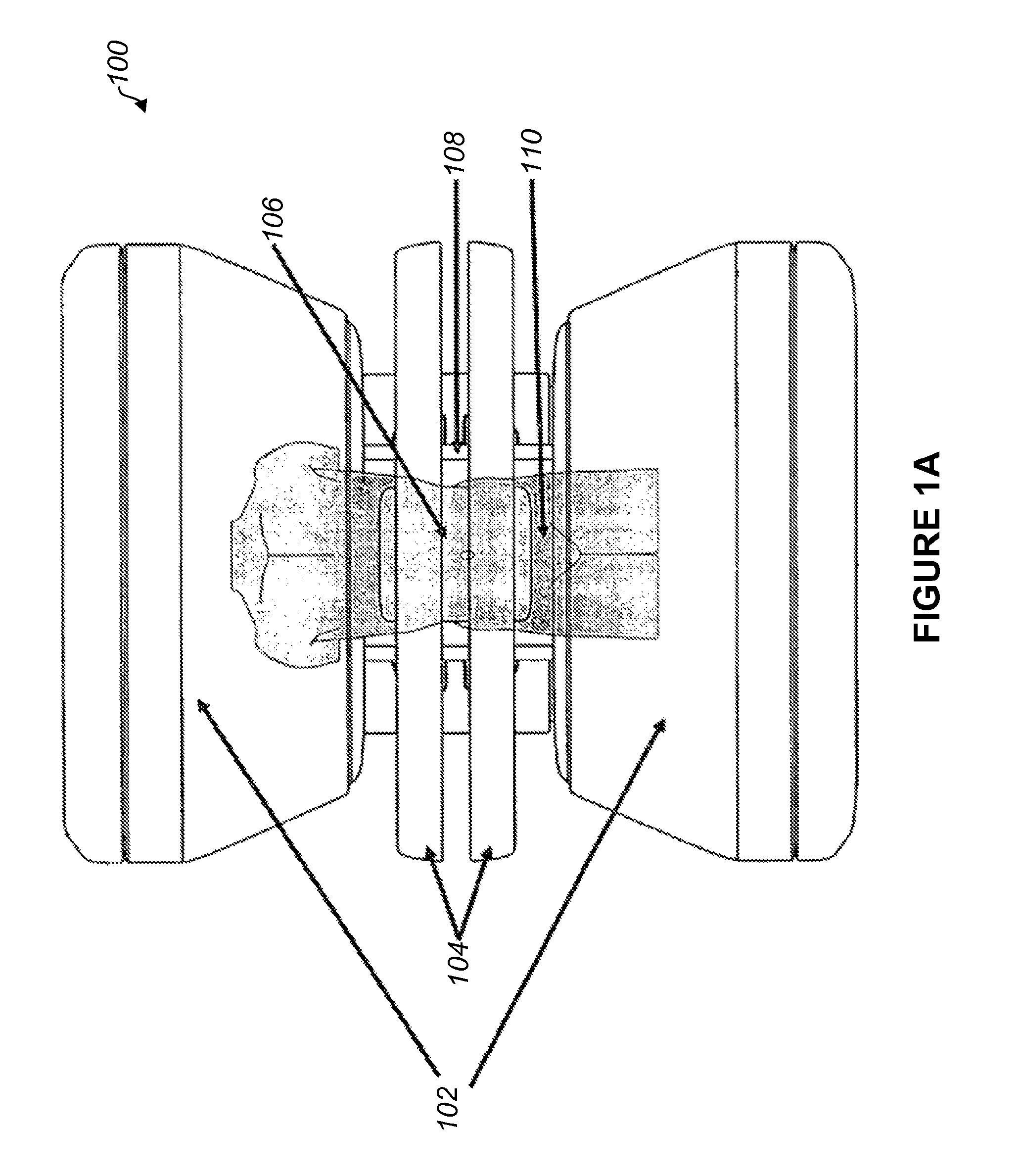
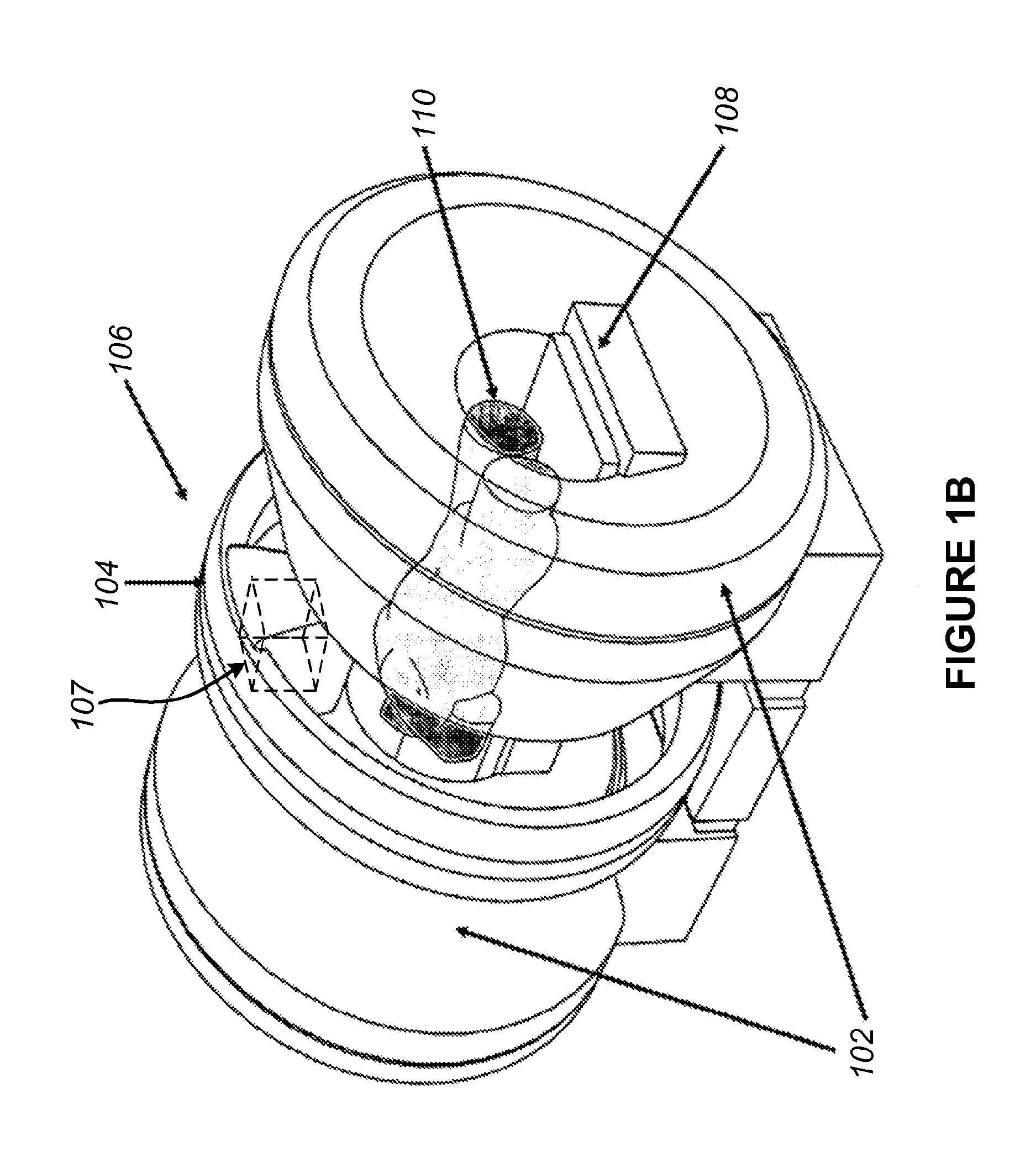
[0038]FIGS. 1A-1E show various views of a split-magnet radiation therapy system 100. FIGS. 1A and 1B show plan and perspective views, respectively, of a split-magnet radiation therapy system 100. The system 100 includes an integrated linear accelerator 107 and MRI system 102, and allows for simultaneous irradiation from the linear accelerator 107 and imaging from the MRI 102. For example, the MRI 102 can be used to pinpoint the location of an object to be irradiated, and this information can be used to control the irradiation from the linear accelerator 107. The present disclosure is not necessarily limited to the specific MRI and linac systems shown in the Figures and referenced herein, but can apply equally to other MRI and linac systems. For example, RF and / or magnetic shielding systems and methods disclosed herein can be used with known MRI and linac systems that may differ from those shown in the Figures and described below.

[0039]The radiation therapy system 100 includes an ope...


PUM


Abstract

A radiation therapy system comprises a magnetic resonance imaging (MRI) system combined with an irradiation system, which can include one or more linear accelerators (linacs) that can emit respective radiation beams suitable for radiation therapy. The MRI system includes a split magnet system, comprising first and second main magnets separated by gap. A gantry is positioned in the gap between the main MRI magnets and supports the linac(s) of the irradiation system. The gantry is rotatable independently of the MRI system and can angularly reposition the linac(s). Shielding can also be provided in the form of magnetic and / or RF shielding. Magnetic shielding can be provided for shielding the linac(s) from the magnetic field generated by the MRI magnets. RF shielding can be provided for shielding the MRI system from RF radiation from the linac.

Description

RELATED APPLICATION[0001]This application is a continuation and claims benefit of priority under 35 U.S.C. §120 of U.S. patent application Ser. No. 12 / 837,309, filed Jul. 15, 2010, entitled “Method And Apparatus For Shielding A Linear Accelerator And A Magnetic Resonance Imaging Device From Each Other”, which claims the benefit of priority under 35 U.S.C. §119 of U.S. Provisional Application No. 61 / 225,771, filed Jul. 15, 2009, entitled “Method And Apparatus For Shielding A Linear Accelerator And A Magnetic Resonance Imaging Device From Each Other”. These references are incorporated herein by reference in their entirety for all purposes.BACKGROUND[0002]1. Technical Field[0003]The present application relates to systems and methods for combined radiotherapy and magnetic resonance imaging, particularly systems and methods that involve shielding magnetic fields and radiofrequency radiation from the radiotherapy and magnetic resonance imaging systems.[0004]2. Related Art[0005]A linear pa...

Claims


Application Information

Patent Timeline
Patent Type & Authority Applications(United States)
IPC IPC(8): A61N5/10G01R33/28A61B5/055G01R33/42
CPCA61N5/1039G01R33/42G01R33/28A61N2005/1089A61N5/1081A61N2005/1094A61N2005/1088A61B5/0555A61N5/1049G01R33/421G01R33/4808A61N2005/1055G01R33/3806A61B5/055
Inventor SHVARTSMAN, SHMARYU M.DEMEESTER, GORDONDEMPSEY, JAMES F.PATRICK, JOHN LESTER
Owner VIEWRAY TECH
Why Eureka
Try Eureka