

Brush design for propeller deicing system
- Summary
- Abstract
- Description
- Claims
- Application Information
AI Technical Summary
Benefits of technology
Problems solved by technology
Method used
Image


Examples
Embodiment Construction
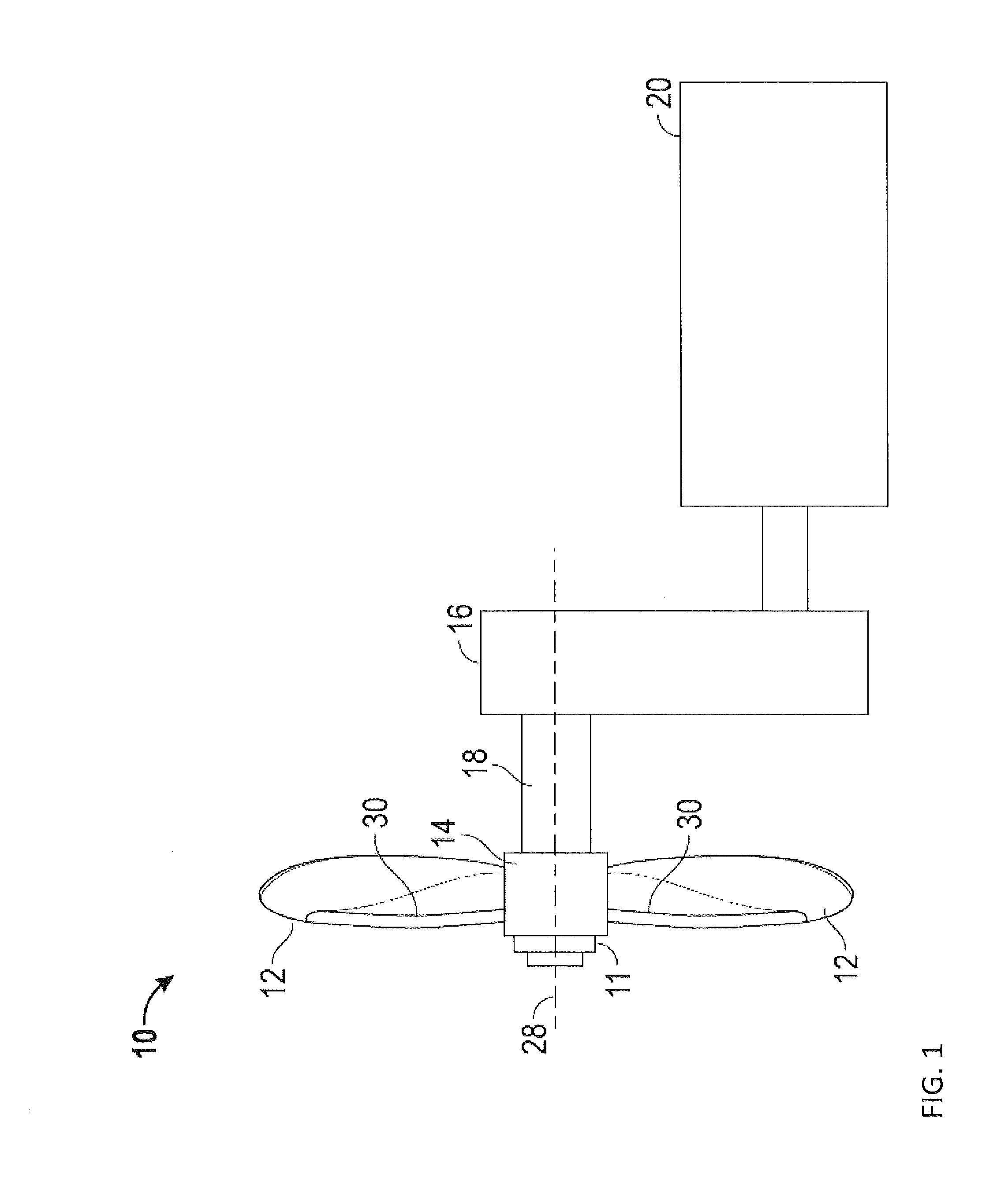
[0014]Shown in FIG. 1 is schematic view of an embodiment of a propeller system 10 for an aircraft. The propeller system 10 includes a propeller assembly having a plurality of propeller blades 12 arranged around a hub 14. A pitch change actuator 11 is connected to an end of the hub 14. The propeller blades 12 include one or more heating elements 30 for deicing of the propeller blades 12. The propeller system 10 is operably connected to a reduction gearbox 16 via a propeller shaft 18, which is in turn connected to an engine 20.
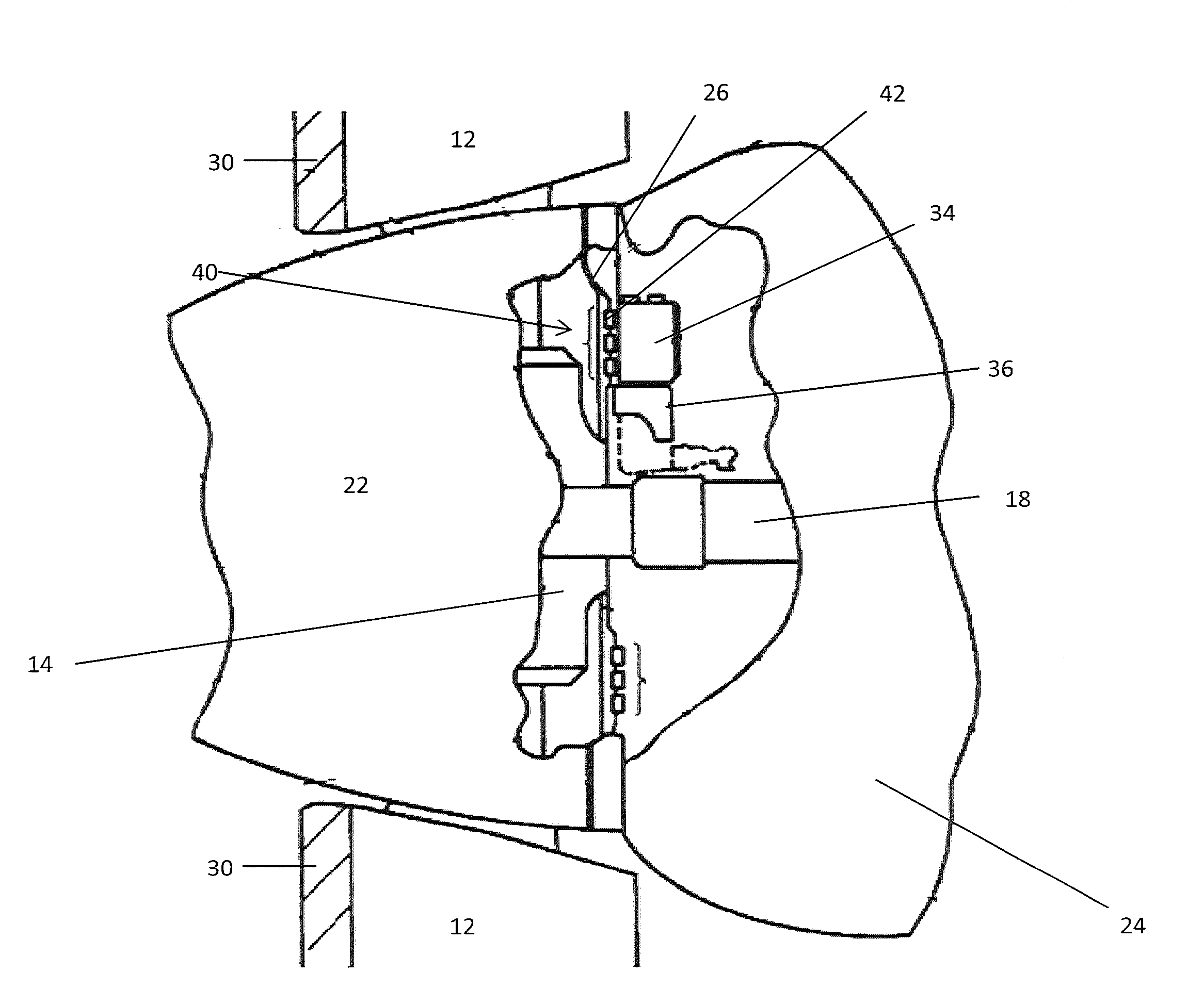
[0015]Referring now to FIG. 2, a spinner 22 encloses the hub 14 which mechanically secures each of the plurality of propeller blades 12 to the propeller shaft 18. The rearward interior portion of the spinner 22, facing the engine cowling 24, includes a bulk head 26. The bulk head 26 is both substantially flat and substantially annular in its geometry, and includes a center hole through which the propeller shaft 18 connects to the hub 14. The exposed surface of t...
PUM
 Abstract
Description
Claims
Application Information