Connector Terminal and Electrical Connector

a technology of connecting terminal and electrical connector, which is applied in the direction of coupling device connection, two-part coupling device, electrical apparatus, etc., can solve the problems of reducing the size of the movable space, the size of the movable space cannot be reduced beyond a certain limit, and it is difficult to reduce the size of the entire electrical connector, so as to achieve the effect of increasing density and reducing the size of the electrical connector

Active Publication Date: 2015-05-14
IRISO ELECTRONICS CO LTD
View PDF3 Cites 17 Cited by
  • Summary
  • Abstract
  • Description
  • Claims
  • Application Information

AI Technical Summary

Benefits of technology

[0027]With the present invention, the size of the electrical connector can be reduced in the width direction of the terminal. Therefore, for example, the size of a floating connector, which in

Problems solved by technology

However, the movable portion, which is a key component of the floating structure, is one of factors that limit reduction in size.
Moreover, the size of the movable space cannot be reduced beyond a certain limit so that the fixed housing and the movable housing c

Method used


Image

  • Connector Terminal and Electrical Connector
  • Connector Terminal and Electrical Connector
  • Connector Terminal and Electrical Connector

Examples


Embodiment Construction

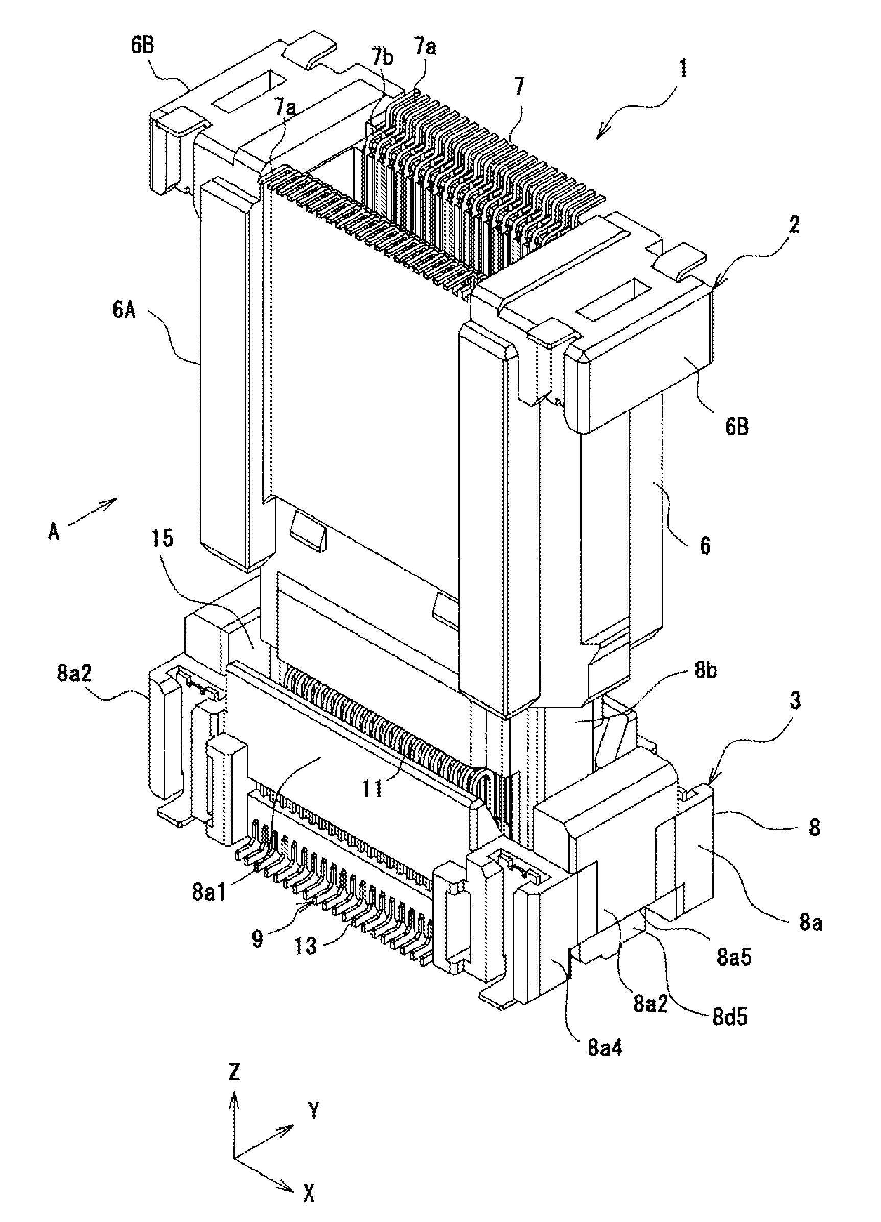
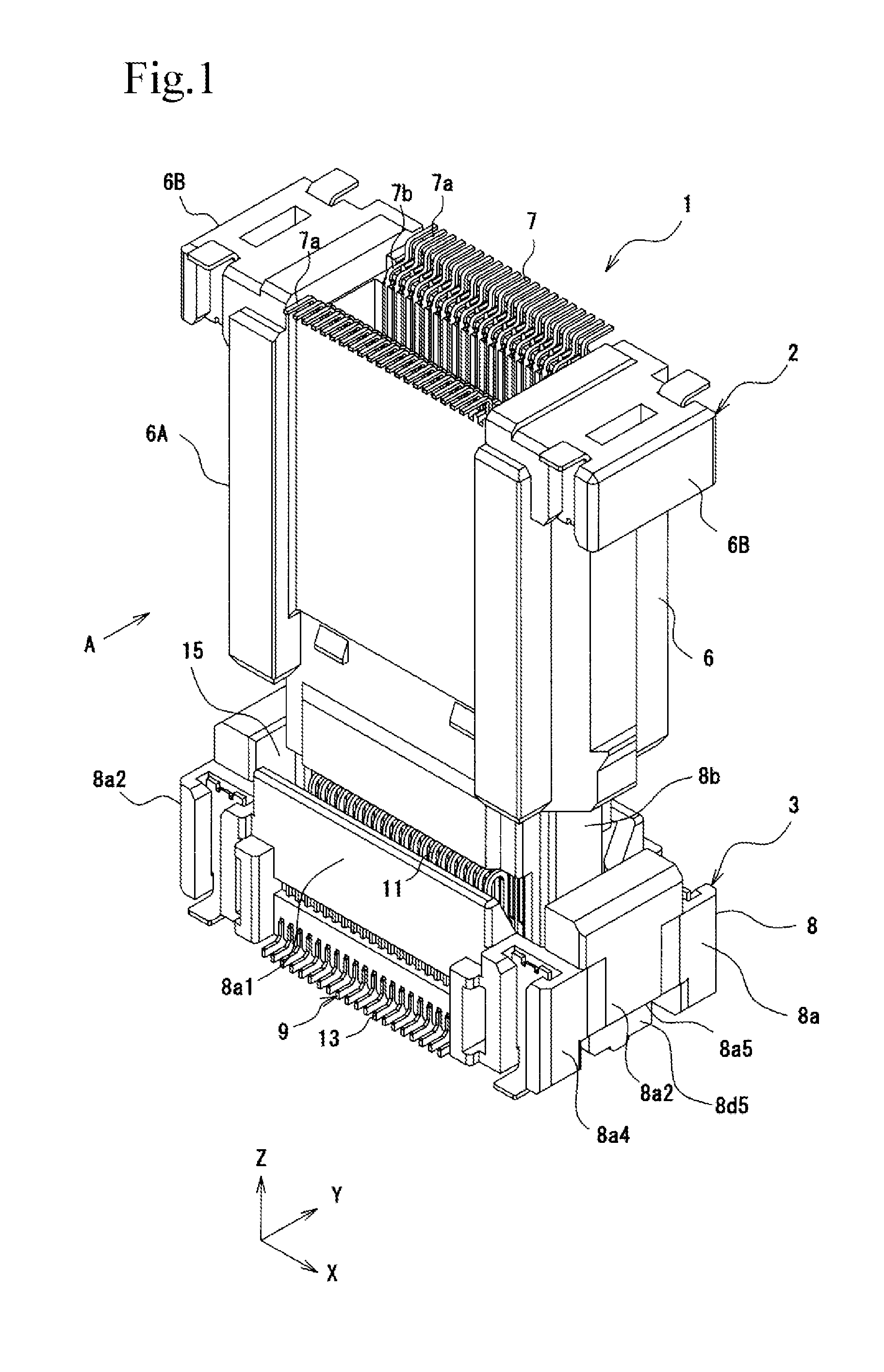
[0041]Hereinafter, an embodiment of an electrical connector according to the present invention will be described with reference to the drawings. In the embodiment below, an example of an interboard connector having a floating function will be described.

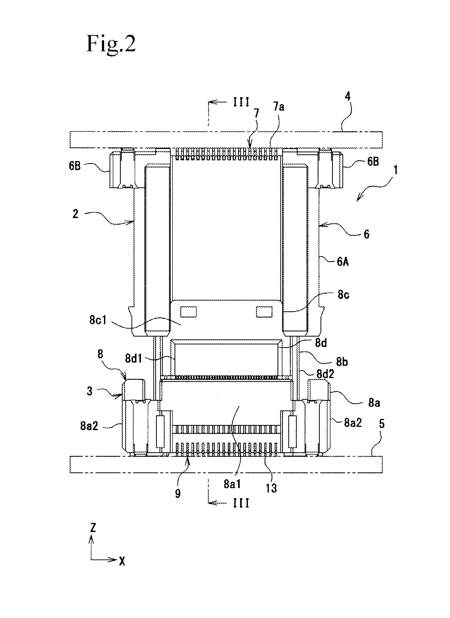
[0042]As illustrated in FIGS. 1 and 2, an electrical connector 1 includes a plug connector 2 and a socket connector 3. As illustrated in FIGS. 2 to 5, the plug connector 2 is mounted on a board 4, and the socket connector 3 is mounted on a board 5. When the plug connector 2 is fitted into the socket connector 3, the board 4 and the board 5 become conductively connected to each other.

[0043]As illustrated in FIGS. 1 to 13, in the specification, claims, and the drawings, the longitudinal direction of the electrical connector 1 will be referred to as the X direction, the transverse direction of the electrical connector 1 will be referred to as the Y direction, and the insertion / extraction direction in which the plug connector 2 is inserte...


PUM


Abstract

A socket terminal includes a movable portion that includes a first extension that extends from a position near a fixed housing in an insertion/extraction direction of a plug connector, a hairpin portion that is continuous with the first extension, and a second extension that is continuous with the hairpin portion and that extends in the insertion/extraction direction toward a movable housing. The movable portion elastically supports the movable housing in such a way that the movable housing is displaceable relative to the fixed housing. The second extension of the movable portion includes a spring portion that is bent in such a way that the width of a gap between the second extension and a base at one end portion of the second extension continuous with the hairpin portion is larger than that at the other end portion of the second extension continuous with the base.

Description

BACKGROUND OF THE INVENTION[0001]1. Field of the Invention[0002]The present invention relates to a connecter terminal and an electrical connector having a floating structure.[0003]2. Description of the Related Art[0004]As the performance and multifunctionality of automobile electronic appliances and consumer electronic appliances have increased, electrical connectors for connecting printed circuit boards (hereinafter, referred to as “boards”) to each other are increasingly used. Moreover, as electronic appliances have been reduced in size, boards have also been reduced in size and component packing density has increased. At the same time, it is necessary to connect the boards with high reliability.[0005]A floating structure is a known technology for increasing the connection reliability of electrical connectors. In general, a floating structure includes a “fixed housing” mounted on a board, a “movable housing” to be fitted with a connection object, and “terminals”. Each of the termi...

Claims


Application Information

Patent Timeline
IPC IPC(8): H01R24/60
CPCH01R24/60H01R12/91H01R13/6315
Inventor SATO, KATSUMASA
Owner IRISO ELECTRONICS CO LTD
Why Eureka
Try Eureka