Fluid-filled vibration damping device and method of manufacturing the same

Active Publication Date: 2015-09-17
TOKAI RUBBER IND LTD
View PDF8 Cites 4 Cited by
  • Summary
  • Abstract
  • Description
  • Claims
  • Application Information

AI Technical Summary

Benefits of technology

[0026]According to the seventh aspect, because of the tapered tubular shape, the tubular fitting member can easily be externally slipped around the second mounting member extending straightly due to the guiding effect of the inner peripheral face of the tapered tubular portion, making the assembly process easier in the non-compressible fluid.
[0027]According to the present invention, the pressure-relieving lip is formed protruding out of the sealing rubber layer, which is depressed on both sides of the pressure-relieving lip by having it pressed against either the second mounting member or the tubular fitting member in the initial stage of the drawing operation applied to the tubular fitting member. This allows the fluid chamber to communicate with the outside through the depressed portion of the sealing rubber layer, so that the internal pressure rise of the fluid chamber caused by the diameter-constricting deformation of the tubular fittin

Problems solved by technology

As a result, the internal pressure of the fluid chamber rises as the amount of diameter-constricting deformation of the tubular fitting member by the drawing thereof is increased, which poses a risk of tilting the second mounting member against the tubular fitting member or generating a positional deviation between them in the direction of detaching from each other du

Method used


Image

  • Fluid-filled vibration damping device and method of manufacturing the same
  • Fluid-filled vibration damping device and method of manufacturing the same
  • Fluid-filled vibration damping device and method of manufacturing the same

Examples


Embodiment Construction

[0034]Embodiments of the present invention will be described below in reference to the drawings.

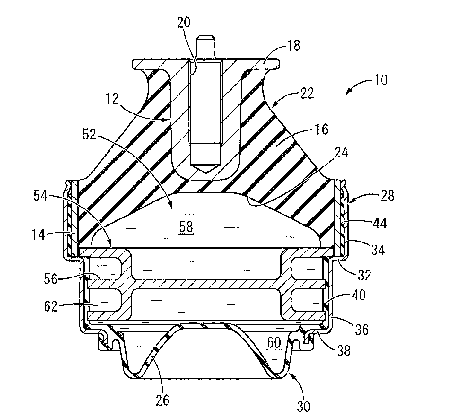
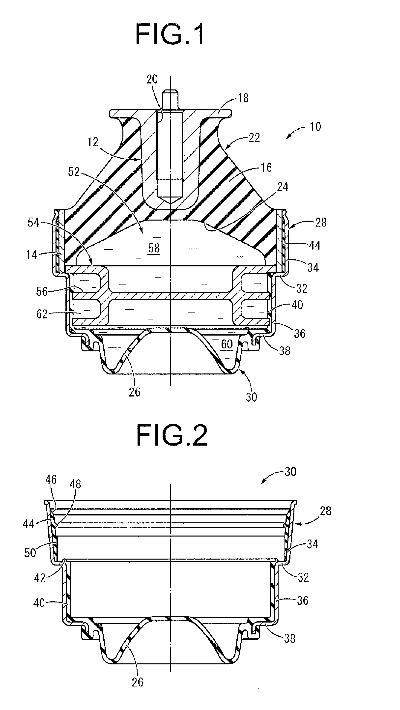
[0035]FIG. 1 shows an automotive engine mount 10 as one embodiment of the fluid-filled vibration damping device with the structure according to the present invention. The engine mount 10 has a structure where a first mounting member 12 and a second mounting member 14 are elastically connected to each other by a main rubber elastic body 16. In the following descriptions, “up-down direction” means the up and down direction in FIG. 1, which is an approximately vertical direction in a state of being mounted to a vehicle.

[0036]More specifically, the first mounting member 12 is a high-rigidity member formed of metal, synthetic resin or the like in an approximate shape of a cylinder as a whole where a flange 18 is integrally formed at the top end protruding toward the outer periphery. In addition, in the first mounting member 12, a screw hole 20 is formed to extend in the up-down direction along...


PUM

PropertyMeasurementUnit
Fractionaaaaaaaaaa
Pressureaaaaaaaaaa
Diameteraaaaaaaaaa

Abstract

A fluid-filled vibration damping device including: first and second mounting members elastically connected by a main rubber elastic body; a tubular fitting member externally slipped around the second mounting member and drawn so as to be externally fitted thereto in a fluid-tight manner; a sealing rubber layer fixed to at least one of an outer peripheral face of the second mounting member and an inner peripheral face of the tubular fitting member so as to be compressed therebetween about an entire circumference; and at least one pressure-relieving lip protruding from the sealing rubber layer and extending toward openings of the second mounting member and the tubular fitting member so as to be pressed against one of the outer peripheral face of the second mounting member and the inner peripheral face of the tubular fitting member in a direction of protrusion.

Description

INCORPORATED BY REFERENCE[0001]The disclosure of Japanese Patent Application No. 2014-054020 filed on Mar. 17, 2014 including the specification, drawings and abstract is incorporated herein by reference in its entirety.BACKGROUND OF THE INVENTION[0002]1. Field of the Invention[0003]The present invention relates to a fluid-filled vibration damping device to be used for an automotive engine mount and the like and a method of manufacturing the same.[0004]2. Description of the Related Art[0005]Conventionally, there has been known a vibration damping device as a kind of vibration damping coupling body or a vibration damping supporting body interposed between the members constituting a vibration transmission system to connect the members to each other in a vibration damping manner, which is applied to an automotive engine mount and the like. Also, as one type of vibration damping device, a fluid-filled vibration damping device is proposed having a non-compressible fluid sealed therein for...

Claims


Application Information

Patent Timeline
IPC IPC(8): F16F13/08F16F13/10
CPCF16F13/08F16F2226/045F16F13/10F16F13/103F16F13/105F16F2230/30Y10T29/49615
Inventor FURUMACHI, NAOKIHIBI, SATORU
Owner TOKAI RUBBER IND LTD
Why Eureka
Try Eureka