Method of joining pipes and fittings

a technology of connecting pipes and fittings, applied in the direction of branching pipes, siphons, synthetic resin layered products, etc., can solve the problems of affecting the quality of pipe components, and requiring considerable force to insert pipes, so as to reduce the risk of deformation, cracking or other structural damage to the piping system components during installation, and the effect of alleviating or eliminating the risk of point loading

Active Publication Date: 2016-03-17
OMACHRON INTPROP
View PDF12 Cites 9 Cited by
  • Summary
  • Abstract
  • Description
  • Claims
  • Application Information

AI Technical Summary

Benefits of technology

[0023]An advantage over traditional methods of restraining piping system components is that by chemically—as opposed to mechanically—bonding the mechanical restraint member to the piping system components, the risk of deformation, cracking, or other structural damage to the piping system components during installation a

Problems solved by technology

Separation of any of the components of the piping system or cracking of any element of the piping system may permit fluid to leak out of the piping system and, e.g., thereby damage the surrounding structure and/or pollute the ground water.
A considerable force is typically required to insert the pipe end past the gasket.
The assembly of push-on fittings can be complicated and time consuming.
A further issue is that many fittings are installed in a trench, making access to the bolts on the bottom of the joint a problem.
Once an installation is complete (e.g. a piping system is buried under a road), accessing the piping system to repair a leak i

Method used


Image

  • Method of joining pipes and fittings
  • Method of joining pipes and fittings
  • Method of joining pipes and fittings

Examples


Embodiment Construction

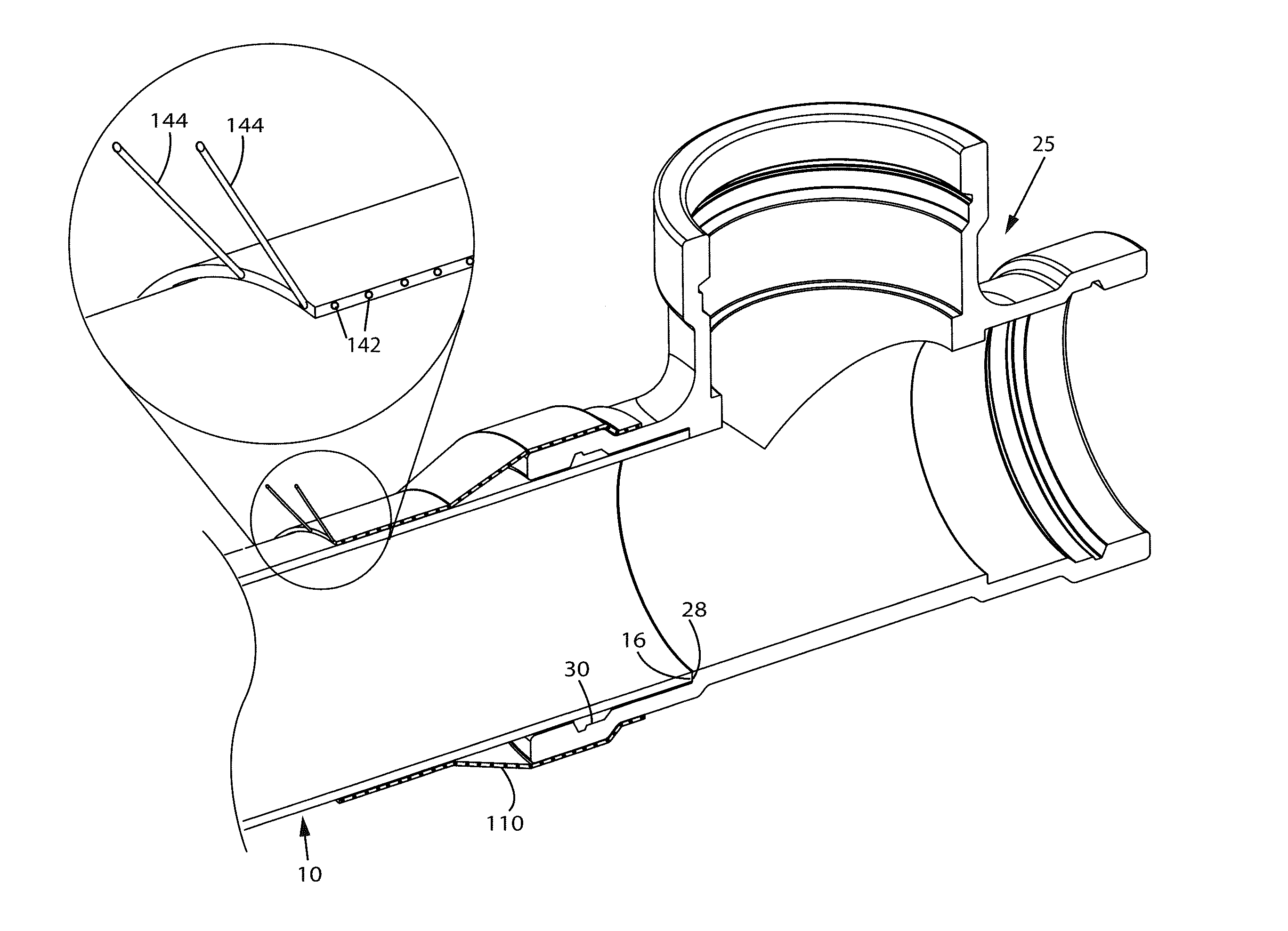
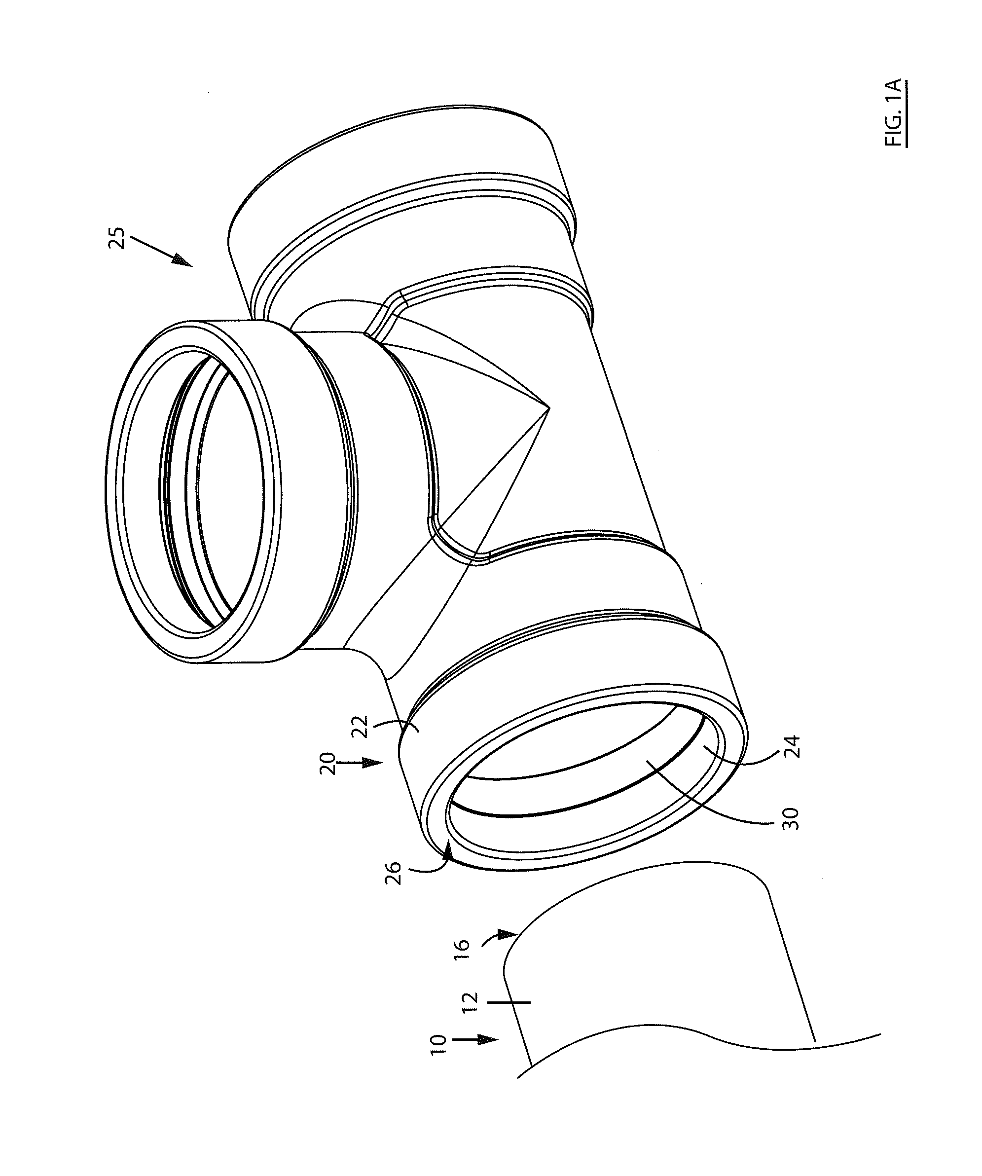
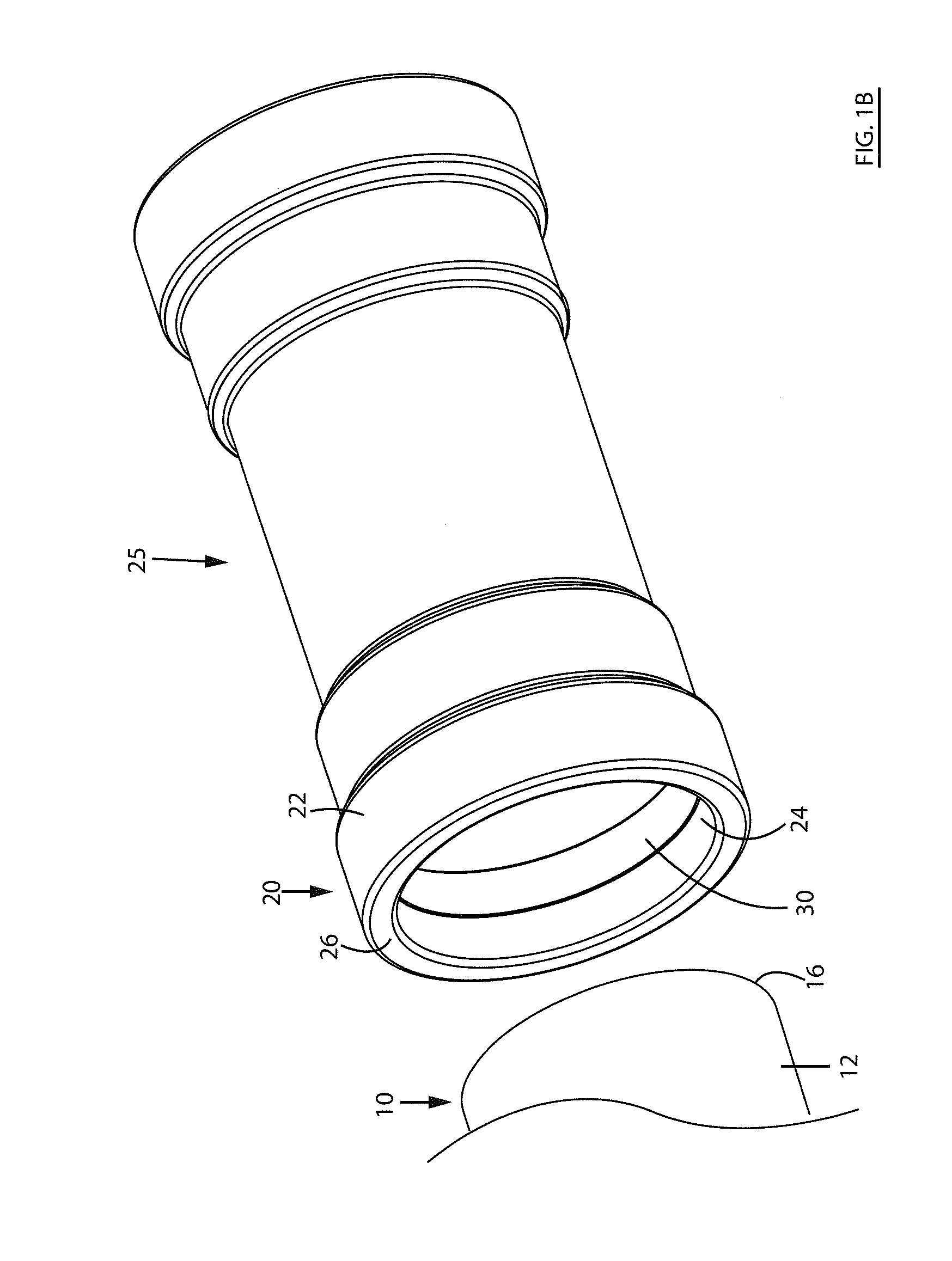
[0142]Various apparatuses, methods and compositions are described below to provide an example of an embodiment of each claimed invention. No embodiment described below limits any claimed invention and any claimed invention may cover apparatuses and methods that differ from those described below. The claimed inventions are not limited to apparatuses, methods and compositions having all of the features of any one apparatus, method or composition described below or to features common to multiple or all of the apparatuses, methods or compositions described below. It is possible that an apparatus, method or composition described below is not an embodiment of any claimed invention. Any invention disclosed in an apparatus, method or composition described below that is not claimed in this document may be the subject matter of another protective instrument, for example, a continuing patent application, and the applicant(s), inventor(s) and / or owner(s) do not intend to abandon, disclaim, or d...


PUM

PropertyMeasurementUnit
Temperatureaaaaaaaaaa
Pressureaaaaaaaaaa
Flexibilityaaaaaaaaaa

Abstract

A method for joining a first conduit section with a second conduit section. The method includes: a) inserting a first end of the second conduit section in an open first end of the first conduit section with a gasket extending between an inner surface of the first conduit section and an outer surface of the second conduit section; b) positioning a flexible substrate having a bonding agent provided on at least a portion of an inner side of the flexible substrate to extend from an outer surface of the first conduit to an outer surface of the second conduit; c) applying pressure to the flexible substrate whereby the bonding agent is pressed against an outer surface of the first and second conduit sections; and d) heating the bonding agent whereby the bonding agent is secured to the outer surface of the first and second conduit sections.

Description

CROSS-REFERENCE TO RELATED APPLICATIONS[0001]This application claims foreign priority benefits under 35 U.S.C. §119 (a)-(d) to Canadian Patent Application no. 2,863,272, filed on Sep. 12, 2014, which is hereby incorporated by reference in its entirety.FIELD[0002]This disclosure relates generally to the connection of pipes and fittings that are used to convey a fluid, and more particularly to a mechanical restraint member to secure components of a piping system to each other and methods for joining pipes and fittings that involves the application of the mechanical restraint member.INTRODUCTION[0003]Piping systems are used to convey liquids and / or gasses to, between, or within, residential, commercial, and / or industrial buildings. For example, most municipalities have a piping system for providing potable and / or non-potable water from one or more reservoirs, pumping stations, and / or water towers to one or more buildings (e.g. residential, commercial, or industrial) and / or other locati...

Claims


Application Information

Patent Timeline
IPC IPC(8): F16L25/00F16L13/10F16L21/03
CPCF16L25/0081F16L21/03F16L13/103F16L17/10F16L21/08F16L41/021F16L43/008F16L47/02F16L47/03F16L47/32B32B5/022B32B5/024B32B15/02B32B15/08B32B15/18B32B15/20B32B27/12B32B27/308B32B27/36B32B27/40B32B1/08B32B3/266B32B2260/021B32B2260/046B32B2262/02B32B2262/0238B32B2262/0253B32B2262/0269B32B2262/06B32B2262/08B32B2262/101B32B2262/106B32B2307/54B32B2307/546B32B2597/00B29C65/18B29C66/0042B29C66/1222B29C66/1224B29C66/52241B29C66/52292B29C66/5344B29C66/7392B29C66/8122B29C66/81455B29C66/81471B29C66/71B29K2023/06B29K2023/065B29K2055/02B29K2069/00B29K2077/00
Inventor CONRAD, WAYNE, ERNEST
Owner OMACHRON INTPROP
Why Eureka
Try Eureka