Pinnacle truss

a pinnacle and truss technology, applied in the direction of girders, joists, trusses, etc., can solve the problems of insufficient overall structure of the frame, stress and strain production in the gap, etc., and achieve the effect of eliminating potential stress and strain and strengthening the overall structur

US20160090733A1Active Publication Date: 2016-03-31CHEUNG CHARLES
16 Cites 3 Cited by

Patent Information

Authority / Receiving Office
US · United States
Patent Type
Applications(United States)
Current Assignee / Owner
Publication Date
2016-03-31

Smart Images

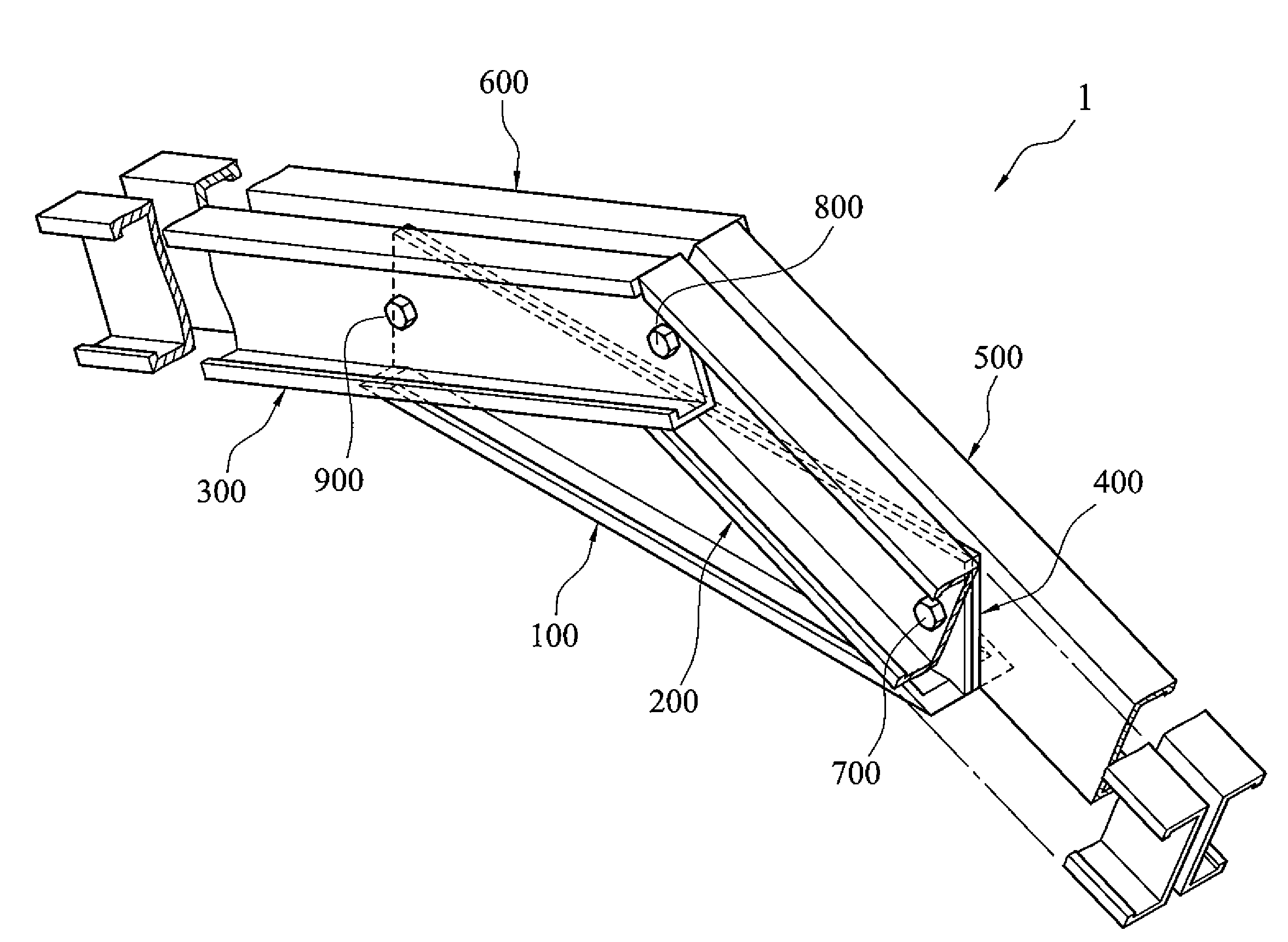
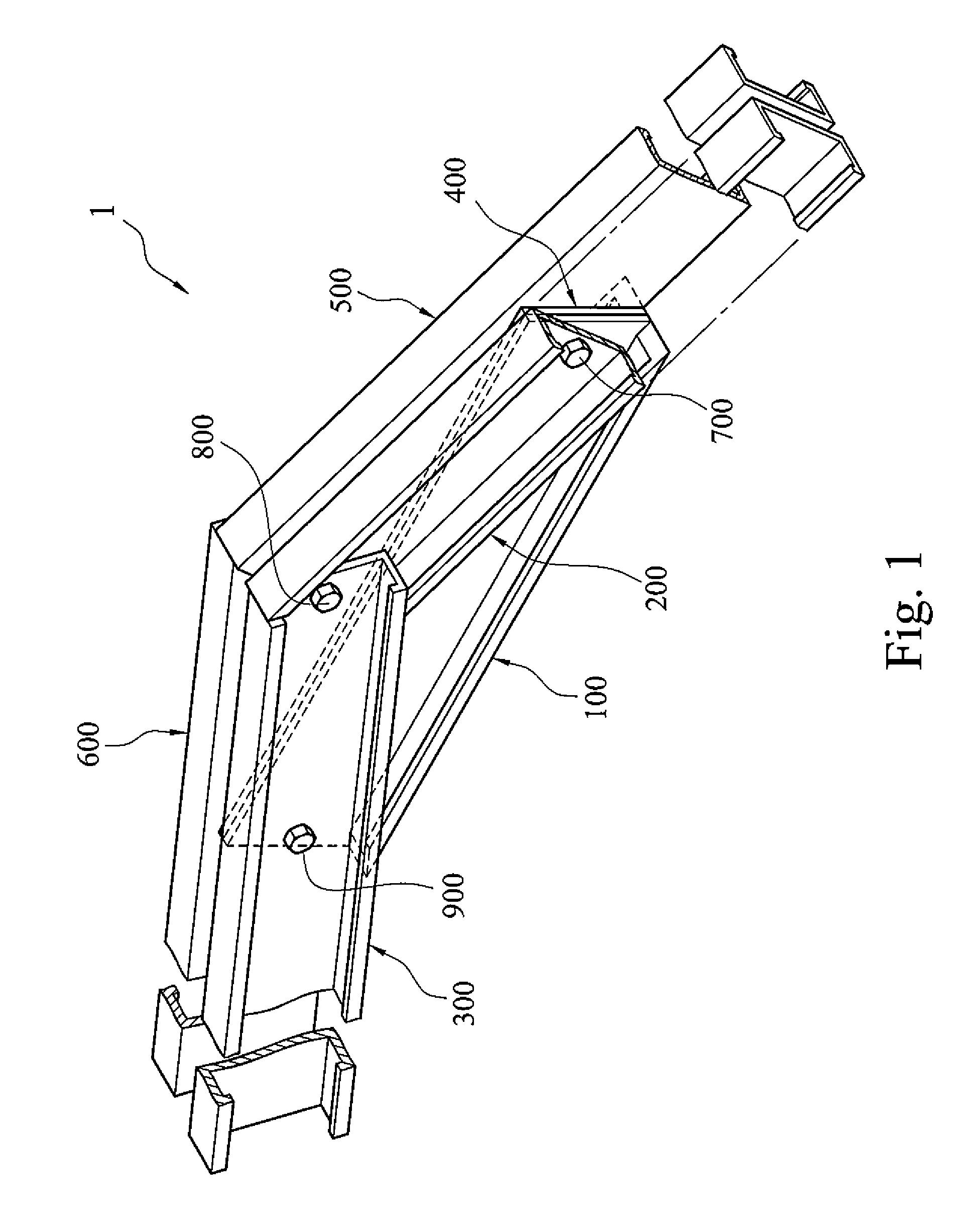
  • Figure 1
    Figure 1
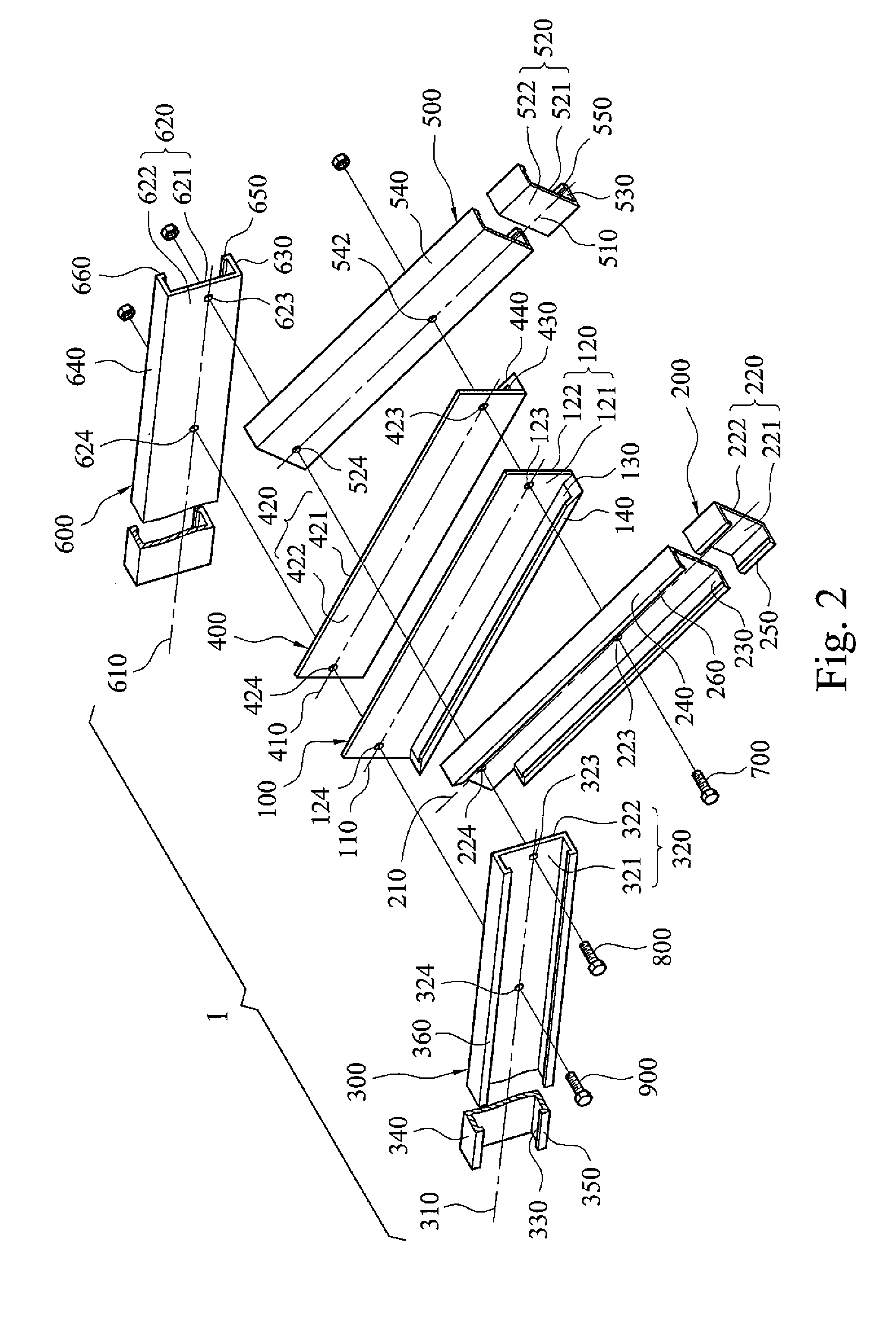
  • Figure 2
    Figure 2
  • Figure 3
    Figure 3
Patent Text Reader

Abstract

A pinnacle truss has a first linear support member, a second linear support member stacked on the first support member and a third linear support member stacked on the first support member and the second linear support member. The first linear support member, the second linear support member, and the third linear support member form a triangular support structure. The first linear support member has an L-shaped cross section. The second linear support member and the third linear support member each has a C-shaped cross section.
Need to check novelty before this filing date? Find Prior Art

Description

FIELD OF THE INVENTION

[0001] This invention relates to a support device, in particular, to a pinnacle truss.BACKGROUND OF THE INVENTION

[0002] The prior frame has a first side C-shaped groove member, a second side C-shaped groove member and an intermediate C-shaped groove member. The first side C-shaped groove member and the second side C-shaped groove member are linked to each other with an angle through the intermediate C-shaped groove member. In other words, a middle section of the first side C-shaped groove member is connected to a most left section of the intermediate C-shaped groove member, a right section of the first side C-shaped groove member is connected to an upper left section of the intermediate C-shaped groove member, a middle section of the second side C-shaped groove member is connected to a most right section of the intermediate C-shaped groove member, and a left section of the second side C-shaped groove member is connected to an upper right section of the intermedia...

Examples

Embodiment Construction

[0015]Referring now to the attached drawings for the description of this invention, various structures, systems and devices are schematically depicted in the drawings only for the purpose of illustration without obscuring this invention by details known by persons skilled in the art. However, it still contains the attached drawings to describe and illustrate the embodiments of this invention. Words and phrases used herein should be understood and interpreted as those with consistent meaning by persons skilled in the art. Terms and phrases consistently used here are not intended to imply specific definition, namely different from general and conventional definition known by persons skilled in the art. Terms or phrases are intended to expand specific definition, for example, definition outsides the understanding by persons skilled in the art. This specific definition will be clearly expressed in this specification in such a way that specific definition is directly and definitely provi...