Double flame polishing method for fiber preforms
Inactive Publication Date: 2002-10-22
SHIN ETSU CHEM IND CO LTD
View PDF10 Cites 4 Cited by
- Summary
- Abstract
- Description
- Claims
- Application Information
AI Technical Summary
Problems solved by technology
If there are some damages and unevenness in the surface of an optical fiber base material, an optical fiber will be cut off during drawing the optical fiber base material to an optical fiber.
Also, the ratio between core diameter and cladding diameter of the optical fib
Method used
View moreImage
Smart ImageViewing Examples
Examples
 PUM
| Property | Measurement | Unit |
|---|---|---|
| Angle | aaaaa | aaaaa |
| Temperature | aaaaa | aaaaa |
| Length | aaaaa | aaaaa |
Abstract
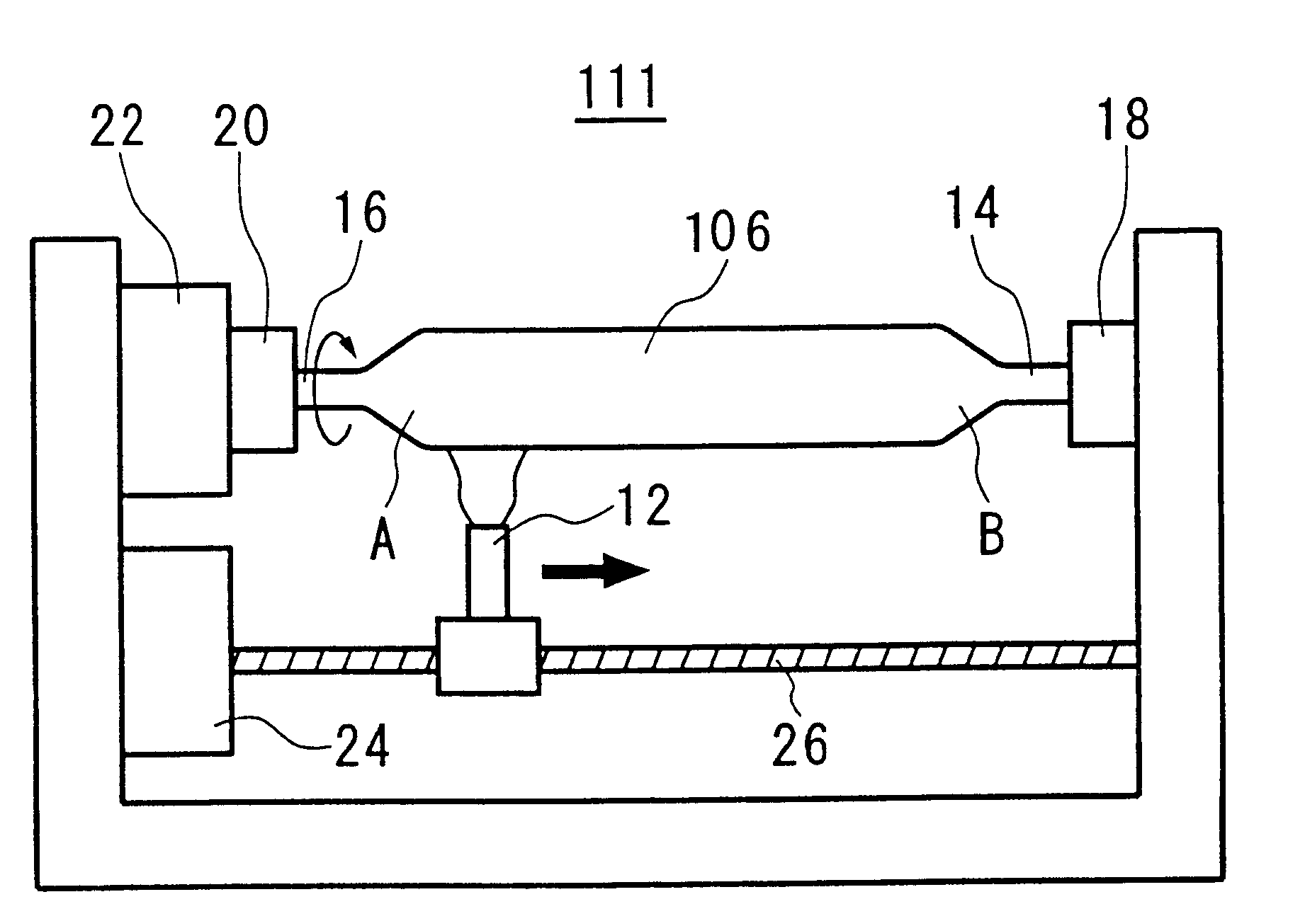
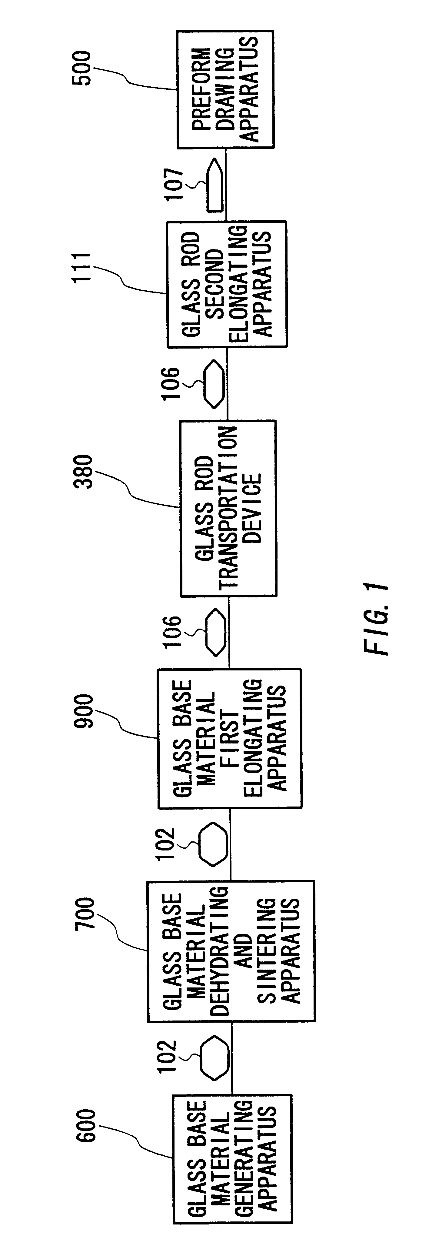
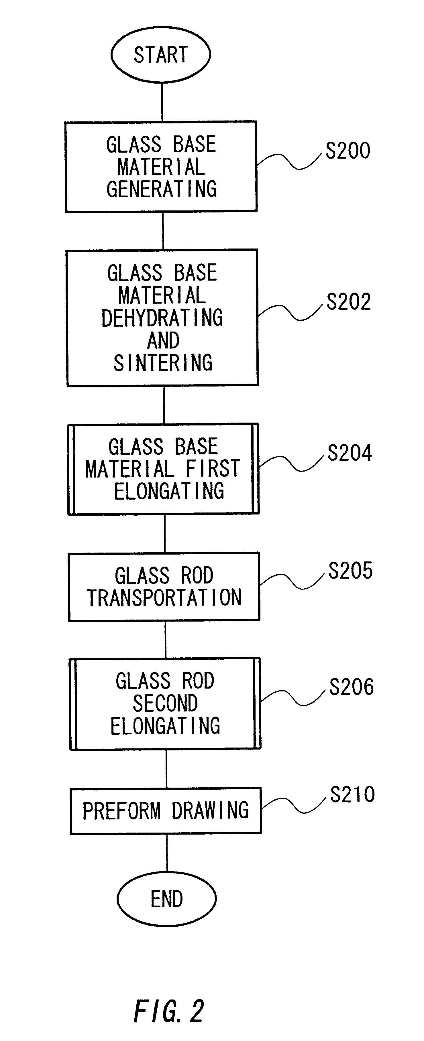
The optical fiber base material heat treatment method can be provided that the first flame polishing heats the surface of the optical fiber base material (106) with fixing a length of the optical fiber base material (106) and the second flame polishing heats the surface of the optical fiber base material (106) by lower temperature than the temperature of the heating of the first flame polishing.
Description
This patent application claims priority based on a Japanese patent application, H11-010023 filed on Jan. 19, 1999, the contents of which are incorporated herein by reference.BACKGROUND OF INVENTION1. Field of the InventionThe present invention is related to an optical fiber heat treatment method that can treat the surface of an optical fiber base material evenly by a flame, and an optical fiber manufacture method using said heat treatment method.2. Description of Related ArtAn optical fiber is manufactured from an optical fiber base material as the raw materials. Principal ingredient of an optical fiber base material is quartz glass. An optical fiber base material is heated and elongated to the predetermined diameter to be an optical fiber preform. An optical fiber preform is drawn to be an optical fiber.If there are some damages and unevenness in the surface of an optical fiber base material, an optical fiber will be cut off during drawing the optical fiber base material to an opti...
Claims
Login to View More Application Information
Patent Timeline
 IPC IPC(8): C03B29/00C03B29/02C03B37/012
CPCC03B29/02C03B37/01237C03B29/06Y02P40/50Y02P40/57
Inventor FUJII, HIDEKINAGAO, TAKAAKIHOSHINO, SHOJISHIMADA, TADAKATSUHIRASAWA, HIDEO
Owner SHIN ETSU CHEM IND CO LTD
Features
- R&D
- Intellectual Property
- Life Sciences
- Materials
- Tech Scout
- Unparalleled Data Quality
- Higher Quality Content
- 60% Fewer Hallucinations
Learn More Browse by: Latest US Patents, China's latest patents, Technical Efficacy Thesaurus, Application Domain, Technology Topic, Popular Technical Reports.
© 2025 PatSnap. All rights reserved.Legal|Privacy policy|Modern Slavery Act Transparency Statement|Sitemap|About US| Contact US: help@patsnap.com


