

Control circuit and method
a technology of control circuit and control circuit, applied in the direction of ac-dc conversion, electrical apparatus, power conversion system, etc., can solve the problem of achieve the effect of reducing energy requirements, reducing energy requirements for the voltage regulation means, and limited energy available for the second voltage waveform
- Summary
- Abstract
- Description
- Claims
- Application Information
AI Technical Summary
Benefits of technology
Problems solved by technology
Method used
Image

Examples
first embodiment
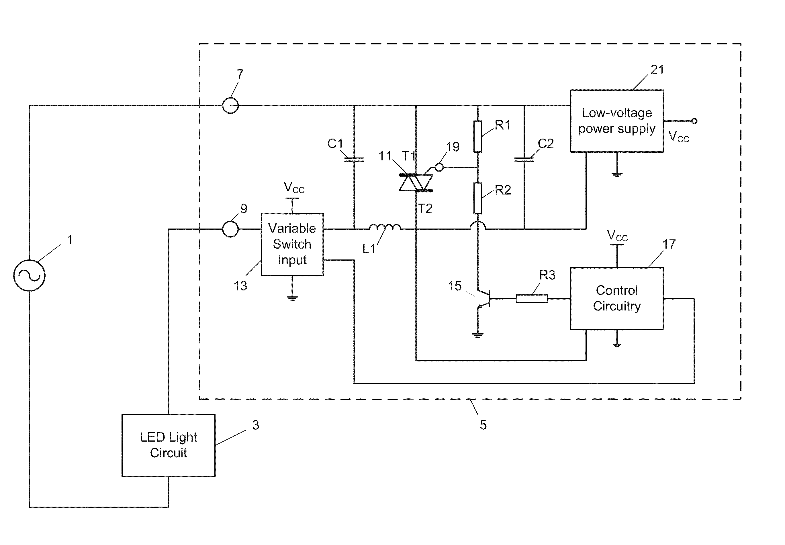
[0029]the invention will now be described with reference to FIGS. 2 to 5.
[0030]FIG. 2 provides an overview of the circuit elements in an arrangement according to the embodiment.
[0031]An AC mains power supply 1 is connected between an LED light circuit 3 and dimmer switch circuit 5. In a typical household / office lighting scenario, LED light circuit 3 may include a large number of LEDs that are controlled by at least one dimmer switch circuit 5. Dimmer switch circuit 5 is connected to AC mains power supply 1 and LED light circuit 3 through input terminal 7 and output terminal 9 respectively.
[0032]Dimmer switch circuit 5 is most easily understood by considering functional circuit components separately. Like a conventional dimmer switch circuit for an incandescent bulb, dimmer switch circuit 5 provides a phase-cut thyristor-type arrangement, using triac 11 as the thyristor-type device.
[0033]In accordance with a user input at variable switch input 13, gate current supply circuitry includ...
PUM
 Abstract
Description
Claims
Application Information