Control circuit for controlling current through a load using a phase-cut thyristor arrangement and method for controlling thereof

a control circuit and load technology, applied in the direction of ac-dc conversion, power conversion systems, electrical apparatus, etc., can solve the problem of limited achieve the effect of reducing the energy requirement of the voltage regulation means, reducing the energy available for the second voltage waveform, and reducing the energy required

Active Publication Date: 2017-06-06
LILY DIGITAL
View PDF16 Cites 0 Cited by
  • Summary
  • Abstract
  • Description
  • Claims
  • Application Information

AI Technical Summary

Benefits of technology

[0010]In some embodiments, the second voltage waveform, has an average magnitude that is less than or equal to that of the first voltage waveform. This may be important when the thyristor-type device is switched to the conducting state early in an AC main half-cycle, because the voltage regulation means only receives power when the thyristor-type device is in a non-conducting state and therefore the amount of energy available for the second voltage waveform is limited. Nevertheless, it has been found that a second voltage waveform with a reduced average magnitude can maintain the thyristor-type device in a conducting state while the reduced energy requirement associated with the reduced average magnitude means that the voltage regulation means is able to supply sufficient energy even when the thyristor-type device is switched to the conducting state early in the AC mains half-cycle.
[0011]Preferably, the first and second voltage waveforms are different, for example, by having different shapes and / or by being spaced apart, or distinct. The second voltage waveform may be continuous with the first voltage waveform, but have a different shape, or voltage profile / level. Alternatively, the gate current supplying means may be arranged to supply no current to the gate for a period of time between the first voltage waveform and the second voltage waveform. In that case, the first and second voltage waveforms may have the same shape / profile, such as identical pulses, but spaced apart, or different profiles spaced apart. Such embodiments can, and are preferably designed to, reduce the energy required from the voltage regulation means. In some cases, at a high brightness level as specified by the variable input device, the gate current supplying means is arranged to supply no current to the gate for a period of time between the first voltage waveform and the second voltage waveform, while at a low brightness level, the second voltage waveform is continuous with the first voltage waveform.
[0013]In some embodiments, the gate current supplying means comprises a microcontroller powered by the voltage regulation means. A microcontroller advantageously is able to control the supply of a gate current while taking up little physical space. In some embodiments, the thyristor-type device is a triac, which has the advantage of allowing bidirectional current flow.
[0014]Preferably, the power consumed by the second waveform is less than that consumed by the first waveform, thereby achieving the goal of the invention without significant increase in energy consumption over the arrangements of the prior art.

Problems solved by technology

This may be important when the thyristor-type device is switched to the conducting state early in an AC main half-cycle, because the voltage regulation means only receives power when the thyristor-type device is in a non-conducting state and therefore the amount of energy available for the second voltage waveform is limited.

Method used


Image

  • Control circuit for controlling current through a load using a phase-cut thyristor arrangement and method for controlling thereof
  • Control circuit for controlling current through a load using a phase-cut thyristor arrangement and method for controlling thereof
  • Control circuit for controlling current through a load using a phase-cut thyristor arrangement and method for controlling thereof

Examples


first embodiment

[0030]the invention will now be described with reference to FIGS. 2 to 5.

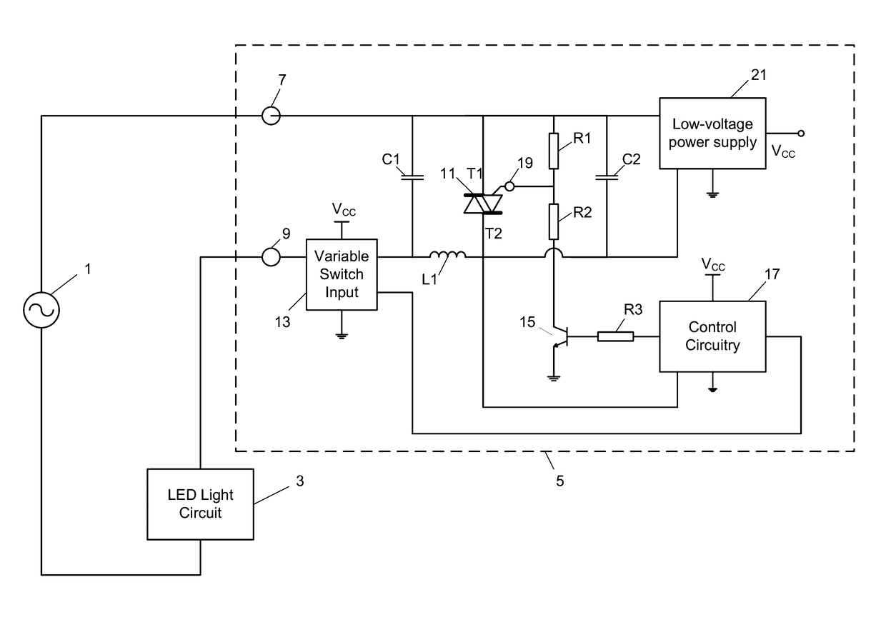
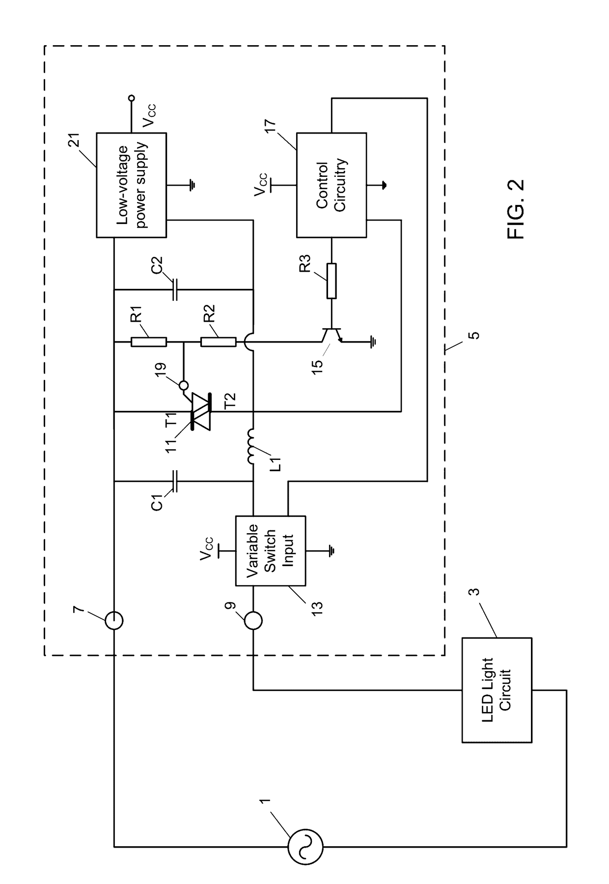
[0031]FIG. 2 provides an overview of the circuit elements in an arrangement according to the embodiment.

[0032]An AC mains power supply 1 is connected between an LED light circuit 3 and dimmer switch circuit 5. In a typical household / office lighting scenario, LED light circuit 3 may include a large number of LEDs that are controlled by at least one dimmer switch circuit 5. Dimmer switch circuit 5 is connected to AC mains power supply 1 and LED light circuit 3 through input terminal 7 and output terminal 9 respectively.

[0033]Dimmer switch circuit 5 is most easily understood by considering functional circuit components separately. Like a conventional dimmer switch circuit for an incandescent bulb, dimmer switch circuit 5 provides a phase-cut thyristor-type arrangement, using triac 11 as the thyristor-type device.

[0034]In accordance with a user input at variable switch input 13, gate current supply circuitry includ...


PUM


Abstract

A dimmer switch for an LED light source utilizes a thyristor-type device (“TTD”) having a first terminal, a second terminal, and a gate terminal. A low-voltage power supply converts alternating voltage into a direct voltage and is connected in parallel with the TTD. Gate current supplying circuitry is provided to supply current to the gate of the TTD, the gate current supplying circuitry powered by the low-voltage power supply and including a variable input device operable to vary a voltage waveform at the gate of the TTD in order to vary a voltage waveform provided at the second terminal. A method for controlling current through the load comprises controlling conductivity of the TTD by varying the voltage waveform at the gate of the TTD including, within a half-cycle of an alternating voltage being applied to the first terminal, applying a first voltage waveform at the gate, so as to place the TTD in a conducting state, followed by applying a second voltage waveform to maintain the TTD in the conducting state.

Description

RELATED APPLICATIONS[0001]This application claims foreign priority to GB 1501260.2, with a filing date of Jan. 26, 2015, incorporated herein in its entirety by this reference.BACKGROUND OF THE INVENTION[0002]The invention relates to a control circuit and method for controlling the power supplied to an electric device. The invention has particular relevance to a dimmer switch for an LED light source.[0003]In recent years, LED light sources have been replacing incandescent bulbs, fluorescent bulbs and other light sources in a variety of lighting applications due to their efficiency, small size and high reliability. However, using a dimmer switch designed for use with one of those conventional light sources with an LED light source may result in sub-optimum performance.[0004]A dimmer switch for an incandescent light source typically uses a phase-cut thyristor arrangement to control the duration of the part of each AC mains half-cycle that is supplied to the incandescent light source. I...

Claims


Application Information

Patent Timeline
Patent Type & Authority Patents(United States)
IPC IPC(8): H05B37/02H05B33/08H02M7/155H05B44/00
CPCH05B33/0815H02M7/1557H05B33/0845Y02B20/347H05B45/10H05B45/3575H05B47/10H05B45/397Y02B20/30
Inventor DOYLE, ANTHONY
Owner LILY DIGITAL
Why Eureka
Try Eureka