Devices and methods for remote therapy and patient monitoring

Active Publication Date: 2022-03-17
ELECTROCORE
View PDF0 Cites 0 Cited by
  • Summary
  • Abstract
  • Description
  • Claims
  • Application Information

AI Technical Summary

Benefits of technology

[0034]A source of power supplies a pulse of electric charge to the electrodes, such that the electrodes produce an electric current and / or an electric field within the patient. The electrical stimulator is configured to induce a peak pulse voltage sufficient to produce an electric field in the vicinity of a nerve such as a vagus nerve, to cause the nerve to depolarize and reach a threshold for action potential propagation. By way of example, the threshold electric field for stimulation of the nerve may be about 8 V / m at 1000 Hz. For example, the device may produce an electric field within the patient of about 10 to 600 V / m (preferably less than 100 V / m) and an electrical field gradient of greater than 2 V / m / mm. Electric fields that are produced at the vagus nerve are generally sufficient to excite all myelinated A and B fibers, but not necessarily the unmyelinated C fibers. However, by using a reduced amplitude of stimulation, excitation of A-delta and B fibers may also be avoided.
[0035]The preferred stimulator shapes an elongated electric field of effect that can be oriented parallel to a long nerve, such as a vagus. By selecting a suitable waveform to stimulate the nerve, along with suitable parameters such as current, voltage, pulse width, pulses per burst, inter-burst interval, etc., the stimulator produces a correspondingly selective physiological response in an individual patient. Such a suitable waveform and parameters are simultaneously selected to avoid substantially stimulating nerves and tissue other than the target nerve, particularly avoiding the stimulation of nerves in the skin that produce pain.

Problems solved by technology

The most significant problem is to assure that the patient is in fact stimulating a vagus nerve.
Failure to do so may be because the stimulator is positioned incorrectly on the neck, or because the amplitude or other stimulation parameters are inappropriate.

Method used


Image

  • Devices and methods for remote therapy and patient monitoring
  • Devices and methods for remote therapy and patient monitoring
  • Devices and methods for remote therapy and patient monitoring

Examples


Embodiment Construction

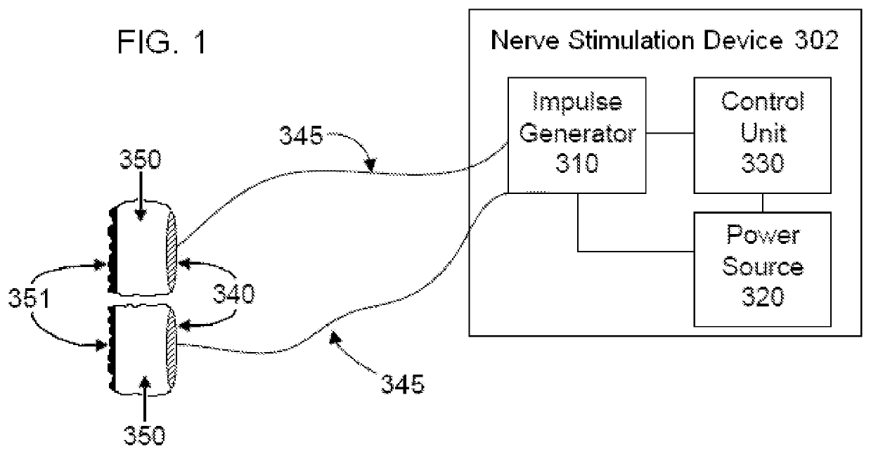
[0068]In the present invention, electrodes applied to the skin of the patient generate currents within the tissue of the patient. An objective of the invention is to produce and apply the electrical impulses so as to interact with the signals of one or more nerves, in order to achieve the therapeutic result. Much of the disclosure will be directed specifically to treatment of a patient by electromagnetic stimulation in or around a vagus nerve, with devices positioned non-invasively on or near a patient's neck. However, it will also be appreciated that the devices and methods of the present invention can be applied to other tissues and nerves of the body, including but not limited to other parasympathetic nerves, sympathetic nerves, spinal or cranial nerves.

Description of the Nerve Stimulating / Modulating Devices

[0069]Devices of the invention that are used to stimulate a vagus nerve will now be described.

[0070]An embodiment of the present invention is shown in FIG. 1, which is a schem...


PUM


Abstract

Systems and methods for remote therapy and patient monitoring are provided. A method comprises contacting an outer skin surface of a patient with a contact surface of a stimulator and transmitting an electrical impulse from the stimulator transcutaneously through the outer skin surface to a nerve within the patient. Data related to parameters of the electrical impulse applied to the nerve is stored and transmitted to a remote source. The data may include duration of treatment, amplitude of the electrical impulse, compliance with a prescribed therapy regimen or other relevant data related to the therapy. The method may further include collecting patient status data, such as symptoms of a medical condition (e.g., severity of a headache) before, during and/or after stimulation. The patient status data is correlated with the treatment data to monitor compliance and/or the effectiveness of the therapy.

Description

CROSS REFERENCE TO RELATED APPLICATIONS[0001]The present application is a continuation of U.S. Nonprovisional application Ser. No. 16,459,391, filed Jul. 1, 2019, which is a continuation of U.S. Nonprovisional application Ser. No. 15 / 018,805 filed Feb. 8, 2016 (now U.S. Pat. No. 10,335,593), which is a divisional of U.S. Nonprovisional application Ser. No. 13 / 872,116 filed Apr. 28, 2013 (now U.S. Pat. No. 9,254,383) issued Feb. 9, 2016, which (1) is a continuation-in-part of U.S. Nonprovisional application Ser. No. 13 / 858,114 filed Apr. 8, 2013 now U.S. Pat. No. 9,248,286 issued Feb. 2, 2016, and (2) is a continuation-in-part of U.S. Nonprovisional application Ser. No. 13 / 603,799 filed Sep. 5, 2012 now U.S. Pat. No. 8,918,178 issued Dec. 23, 2014, which is a continuation-in-part of U.S. Nonprovisional application Ser. No. 13 / 222,087 filed Aug. 31, 2011 now U.S. Pat. No. 9,174,066 issued Nov. 3, 2015, which is a continuation-in-part of U.S. Nonprovisional application Ser. No. 13 / 183,...

Claims


Application Information

Patent Timeline
Patent Type & Authority Applications(United States)
IPC IPC(8): A61B5/394A61N1/36A61B5/00
CPCA61B5/394A61N1/36021A61B5/7264A61B5/7267A61B5/4035A61B5/02405A61B5/4803A61B5/4836A61N1/36031A61N1/36034A61B5/4041A61B2560/0456A61N2/006A61N2/02G16H20/30G16H40/67A61B5/6822A61B2090/3941A61N1/40A61B5/687
Inventor SIMON, BRUCE J.ERRICO, JOSEPH P.
Owner ELECTROCORE
Why Eureka
Try Eureka