Rear derailleur device for a bicycle shifting system

a technology of shifting system and rear derailleur, which is applied in the direction of gear control, belt/chain/gearring, mechanical apparatus, etc., can solve the problems of unfavorable assembly of this kind, and achieve the effect of convenient threading of the back wheel, convenient assembly and simplified chain assembly

Active Publication Date: 2013-05-23
SRAM
View PDF1 Cites 22 Cited by
  • Summary
  • Abstract
  • Description
  • Claims
  • Application Information

AI Technical Summary

Benefits of technology

[0008]In contrast to the prior art that provides either for a passive locking device or no locking device at all, which is why it does not offer a satisfactory remedy for ease of assembly when installing the back wheel, the present invention provides for the derailleur device to be brought into an assembly state, so to speak, in an active manner and for it to be able to be held therein. This is achieved in that the locking device is brought from the passive position, in which it allows for conventional operation of the derailleur device without compromise, into the locking active position, in which it fixes the derailleur device in place in a predetermined operating position and maintains it, so to speak, in a state of ease of assembly, whereby it allows for easy threading of the back wheel into the bicycle frame. During the threading action, the installer must no longer also pay attention to manipulating and positioning the derailleur device itself. Instead, with the derailleur device according to the invention, the installer can move the derailleur device in advance from the passive position thereof into the locking active position thereof and thus maintain the locking device in a desired position for ease of assembly, meaning in the locking position in which the chain guide device is positioned and held for easy assembly of the back wheel.
[0009]The present invention thus allows for pre-positioning the derailleur device for assembly and holding it in this position until the assembly of the back wheel has been completed. During this step, or as a consequence thereto, it is possible to return the locking device automatically, upon operating the gear shifter or by actuating the locking element, from the active position into the passive position thereof and a conventional operating state in which switching of the gears is possible.
[0010]Furthermore, the present invention also simplifies the assembly of the chain because the same can be guided with more ease, due to the return sprockets of the derailleur device

Problems solved by technology

It has become clear, however, that particularly when the back wheel is disassembled from and then reassembled with such bicycle shifting systems, such as for the purpose of repair work or for returning the bicycle from a transportation state into a ready-to-ride state, particularly “threading” the axle of the back wheel into certain receiving areas of the rear fork of the frame causes difficulties especially if a derailleur device of this kind is provided with a rear derailleur device.
Furthermore, said installer must also move oil-lubricated and often soiled parts therein in an effort to position the derailleur device into a position that is conducive to assembly, which is not desired.
Finally, in some constructions, it is even required for the installer to touch the lubricated and typically soiled chain.
An assembly of this kind is not pleasant.

Method used


Image

  • Rear derailleur device for a bicycle shifting system
  • Rear derailleur device for a bicycle shifting system
  • Rear derailleur device for a bicycle shifting system

Examples


Embodiment Construction

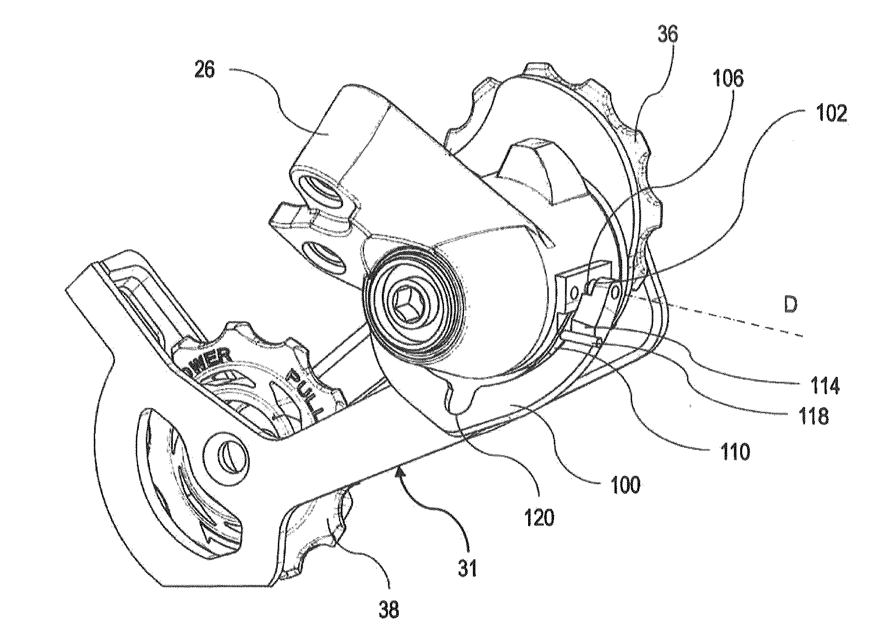
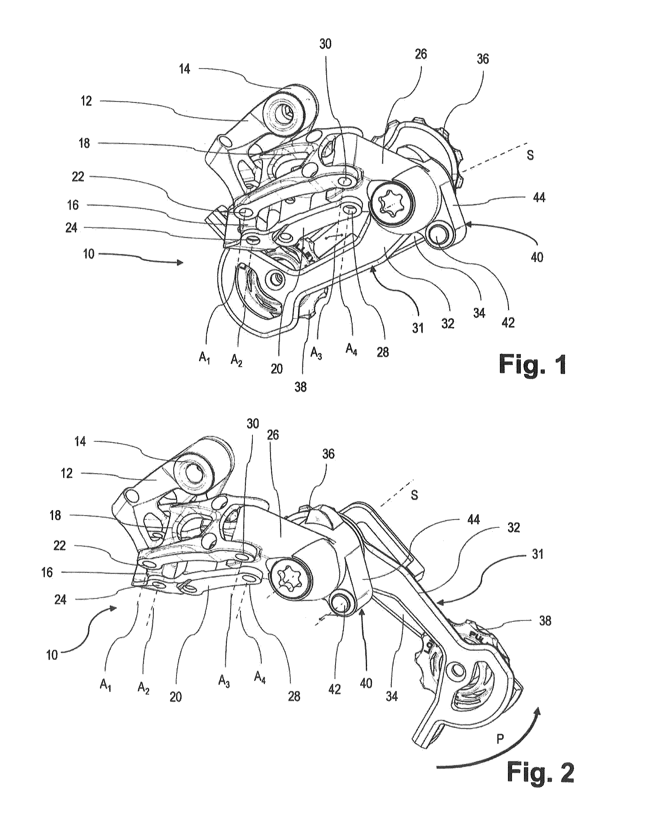
[0034]FIGS. 1 and 2 show a spatial representation of a derailleur device in form of a chain derailleur fastenable to the fork of a back wheel of a bicycle frame, generally designated by the numeral 10. The derailleur device 10 includes a base body 12 that can be fastened by means of a mounting eyelet 14 in a manner known from the prior art to the bicycle frame. The base body 12 is offset multiple times and includes at the end thereof that is directed away from the mounting eyelet 14 a support portion 16. Two pivot arms 18, 20 are pivotably supported by means of support pins 22, 24 on this support portion 16 in relation to the base body 12. At the free ends of the pivot arms 18 and 20 that are directed away from the base body 12, the same are also pivotably connected to a movable element 26. Again, the support pins 28, 30 serve for this purpose as well. The support axes A1, A2, A3, A4 of the respective pivotable support are parallel in relation to each other and constitute, in an axi...


PUM


Abstract

A derailleur device, particularly a rear derailleur, includes at least one locking device for locking a chain guide at least in one locking position that is different from the starting position in relation to a movable element, and it is provided therein that the locking device includes a locking element displaceable between a passive position, in which the chain guide is released in relation to the movable element, and at least one active position, in which the chain guide is held in the at least one locking position.

Description

BACKGROUND OF THE INVENTION[0001]The present invention relates to a derailleur gear changing device for a bicycle shifting system, particularly a rear derailleur.[0002]A derailleur device is known from the prior art. U.S. Pat. No. 3,973,447 specifies a derailleur device in which a chain guide device is configured having two return sprockets. By means of a fixedly disposed locating pin, it is possible to lock the chain guide device in a predetermined deflection position in relation to a movable element to which the chain guide device is pivotably fastened.[0003]As further prior art, reference is being made to documents DE 2 153 407 A1 and DT 25 57 975 B1.[0004]Bicycle shifting systems that provide for a sprocket cassette having a plurality of sprockets on the rear axle of a bicycle, wherein depending on the selected gear the chain is positioned on larger or smaller sprockets by means of the derailleur device are widely used and, in the meantime, have become reliable in terms of their...

Claims


Application Information

Patent Timeline
Patent Type & Authority Applications(United States)
IPC IPC(8): B62M9/124
CPCB62M9/1244B62M9/124
Inventor BOHM, ROBERTHARCKE, TOBIASBENZ, ANDREASRODEGRO, OLIVER
Owner SRAM
Why Eureka
Try Eureka