Nerve stimulator system

a stimulator and energy technology, applied in the field of energy impulse delivery, can solve the problems of mechanical stress and the resulting chronic tissue response, energy source would also and energy source would likely have the disadvantage of having to be placed clos

Active Publication Date: 2015-05-07
ELECTROCORE
View PDF11 Cites 20 Cited by
  • Summary
  • Abstract
  • Description
  • Claims
  • Application Information

AI Technical Summary

Benefits of technology

[0013]The proximity problem would also not arise if higher-frequency beamed electromagnetic waves were used to supply power as now described. Recently, systems have been developed that power implanted pulse generators (or their rechargeable battery) using electromagnetic fields with frequencies on the order of 300 MHz to 10 GHz. An advantage of using these frequencies is that it does not ordinarily require the source of the fields be in the immediate proximity of the receiving antenna within the implanted device. For example, a horn antenna with a waveguide may be used to direct the radiation from its source to a receiving implant antenna that is several meters away from the horn. Some of these devices may operate either in the inductive mode that was described in a previous paragraph, or in the higher frequency mode wherein the electromagneti

Problems solved by technology

Intrinsic limitations of such coil-based powering systems are that the source oscillating magnetic field must be in close proximity to the implanted pickup coil in order to transfer the energy efficiently (e.g., applied to the patient's skin), and the source and pickup coils have to be optimally oriented with respect to one another.
The stimulators could also be powered by ultrasound or infrared light, in which case the energy source would also likely have the disadvantage of having to be placed close to the implant [ABDO A, Sahin M, Freedman D S, Cevik E, Spuhler P S, Unlu M S. Floating light-activated microelectrical stimulators tested in the rat spinal cord.
However, that potential source is generally limited to situations in which very little power is needed for the device, or the environment contains an unusually high level of ambient electromagnetic energy [E. M. YEATMAN.
In addition to the need to replace a battery, another disadvantage of conventional implanted vagus or peripheral nerve stimulation systems is the mechanical stress and the resulting chronic tissue response caused by the constant movement of tethering electrical cables that are connected to the pulse generator.
Furthermore, the cables may break, and motion of the cables may caus

Method used


Image

  • Nerve stimulator system
  • Nerve stimulator system
  • Nerve stimulator system

Examples


Embodiment Construction

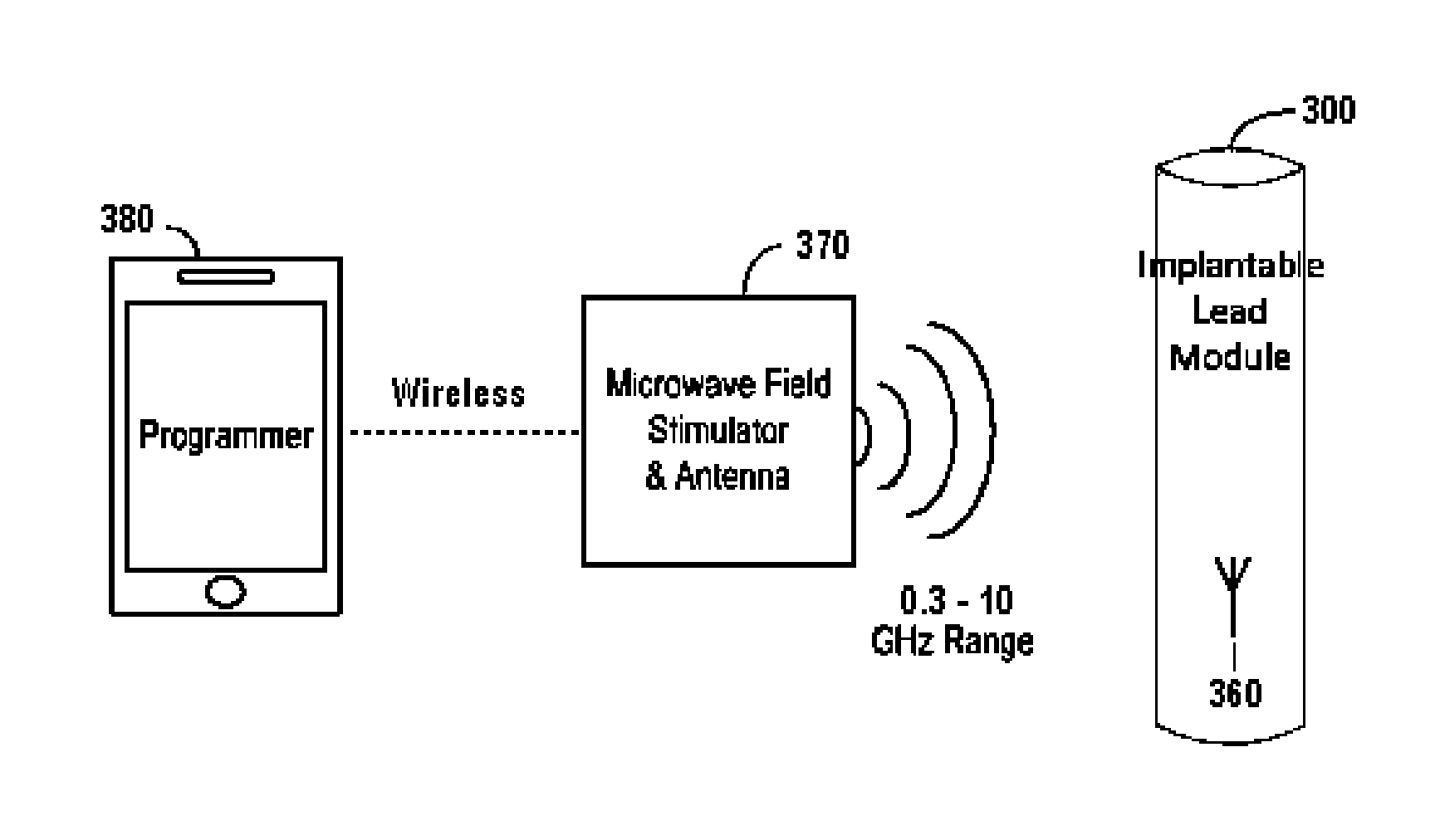
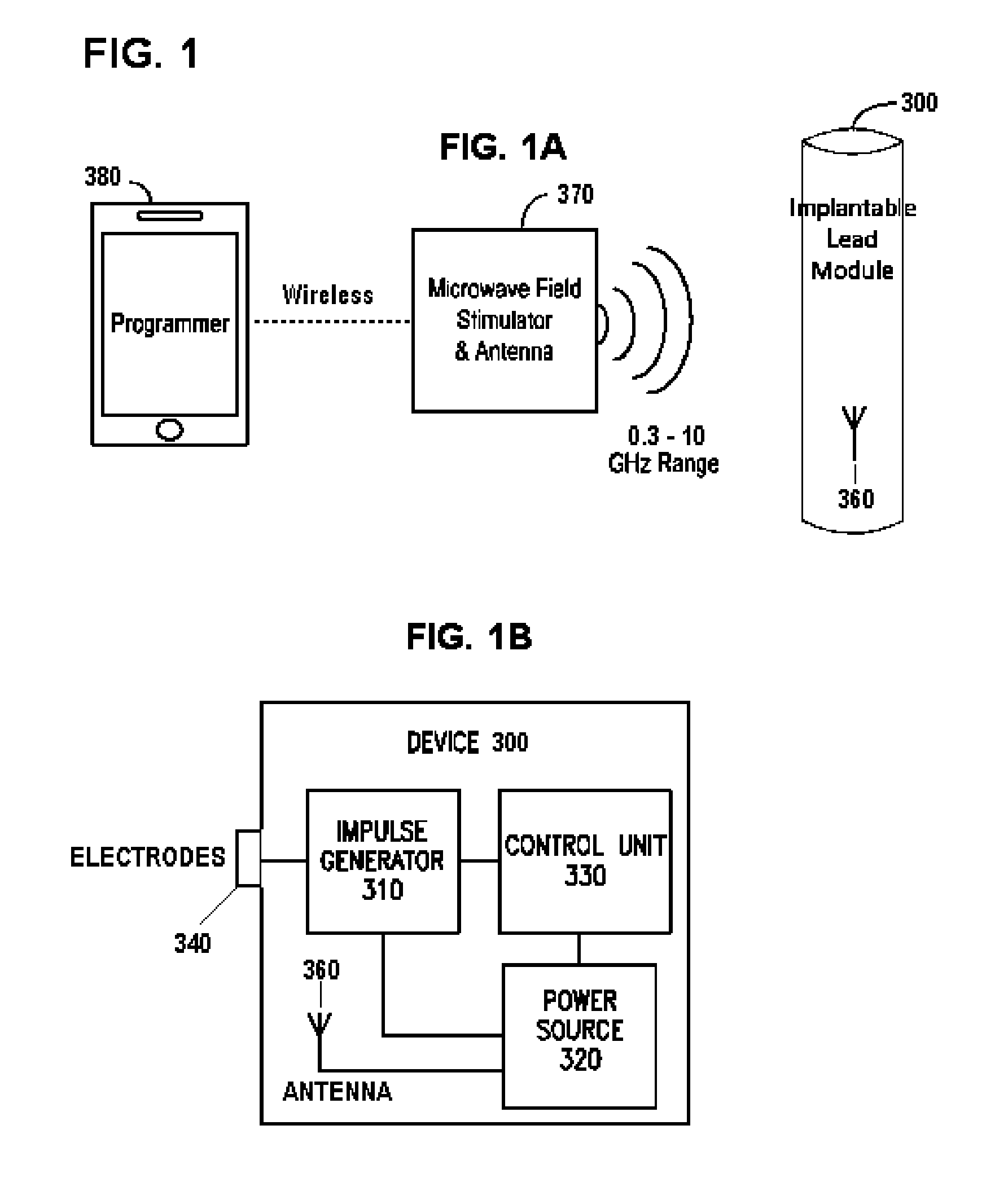
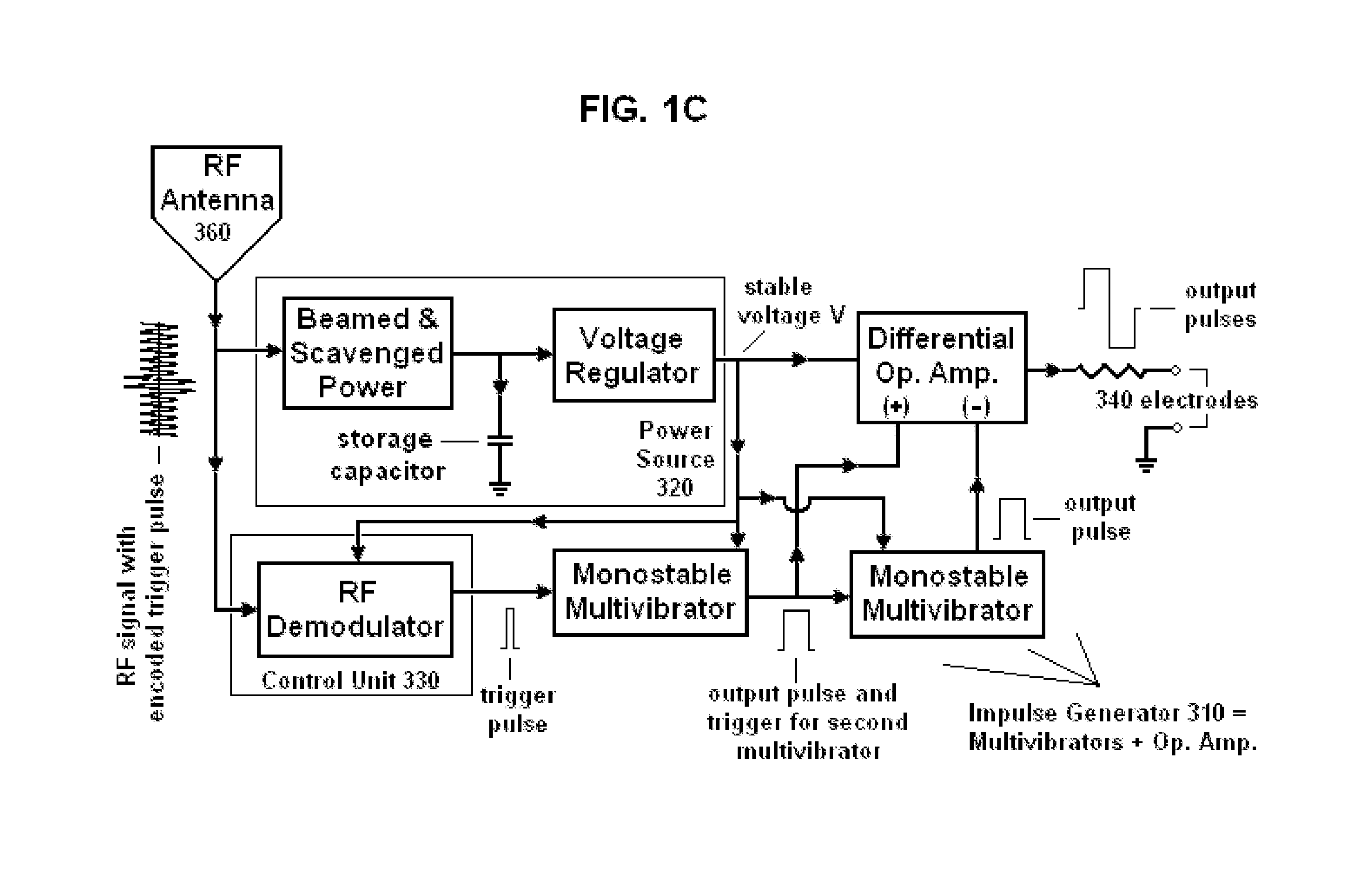
[0057]In one or more embodiments of the present invention, electrical energy is applied in a patient to a target region within or around the carotid sheath (also called the carotid neurovascular bundle) to treat a patient's ailment. The invention is particularly useful for applying electrical impulses that ultimately interact with the signals of a vagus nerve, which lies within the carotid sheath, to achieve a therapeutic result. The nerve stimulation may result in benefits to the patient such as: relaxation of the smooth muscle of the bronchia, increase in blood pressure associated with orthostatic hypotension, reduction in blood pressure, treatment of epilepsy, treating ileus conditions, depression, anaphylaxis, obesity, a neurodegenerative disorder such as Alzheimer's disease, migraine and other types of headache, rhinitis, sinusitis, asthma, atrial fibrillation, autism, gastroparesis and other functional gastrointestinal disorders, and / or any other ailment that may be affected b...


PUM


Abstract

Devices, systems and methods for applying electrical impulse(s) to one or more selected nerves are described. An electrical stimulator is introduced through a to a target location within, adjacent to, or in close proximity with, the carotid sheath. The stimulator has an antenna that allows it to be powered solely by far-field or approximately plane wave electromagnetic radiation, having frequencies in the range of 0.3 to 10 GHz. Electrical impulses are applied through the stimulator to a vagus nerve to stimulate, block or otherwise modulate activity of the nerve and treat the patient's condition. The stimulator uses an adjustable number of fixed voltage (or fixed current) pulses with fixed duration to elicit desired changes in nerve response, the timing of which are controlled by an external power transmitter and controller.

Description

FIELD[0001]The field of the present invention relates to the delivery of energy impulses (and / or fields) to bodily tissues for therapeutic purposes. The energy impulses (and / or fields) that are used to treat those conditions comprise electrical and / or electromagnetic energy, which are delivered to nerve or other tissue of a patient.BACKGROUND OF THE INVENTION[0002]The use of electrical stimulation for treatment of medical conditions is well known. One of the most successful applications of modern understanding of the electrophysiological relationship between muscle and nerves is the cardiac pacemaker. Although origins of the cardiac pacemaker extend back into the 1800's, it was not until 1950 that the first practical, albeit external and bulky, pacemaker was developed. The first truly functional, wearable pacemaker appeared in 1957, and in 1960, the first fully implantable pacemaker was developed.[0003]Around this time, it was also found that electrical leads could be connected to t...

Claims


Application Information

Patent Timeline
IPC IPC(8): A61N1/36
CPCA61N1/3605A61N1/36175A61N1/36153A61N1/36053A61N1/36171A61N1/37205A61N1/37223A61N1/3756A61N1/3787
Inventor SIMON, BRUCE J.ERRICO, JOSEPH P.MENDEZ, STEVEN
Owner ELECTROCORE
Why Eureka
Try Eureka