Graphic-arts laser imaging with reduced-length laser cavities and improved performance

a laser cavity and laser technology, applied in thermography, manufacturing tools, active medium materials, etc., can solve the problems of reducing the desired image quality, reducing the offset angle, and affecting the operation of the laser, so as to reduce the amount of bulk tensing, and improve the effect of laser operation

Inactive Publication Date: 2009-04-28
MARK ANDY
View PDF16 Cites 2 Cited by
  • Summary
  • Abstract
  • Description
  • Claims
  • Application Information

AI Technical Summary

Benefits of technology

[0009]In accordance with the present invention, cavity lasers exhibit a relatively high beam quality (e.g., M2<1.25) despite a relatively small cavity length (e.g., 50-53 mm) for a high (e.g., ≧10 watt) output power device. This enables the construction of physically smaller laser and optical assemblies without sacrificing performance. The present invention also facilitates reduction of optical photonic interference, which can impair imaging performance. In one illustrative embodiment, laser and optical assemblies utilize an aperture defined within an optical barrier element to reduce the divergence of the light beam emanating from a diode-pumping laser. This divergence-reduced light beam is further focused onto a “host” laser crystal (e.g., Nd:YVO4, Nd:GdVO4, Nd:YLF, Nd:YAG) with a relatively reduced dopant level (e.g., about 0.2-0.5%) so as to reduce the amount of bulk tensing occurring therein. This reduced doping level allows the absorption of the pump energy to take place over a longer length of the crystal, resulting in a more uniform crystal heating. The size of the aperture, coupled with the reduced crystal doping level reduces the effective aperture of the host crystal; this facilitates use of an output coupler / Lens with a greater-than-normal curvature, which, in turn, reduces the length of the laser cavity. Moreover, the length of the crystal may be reduced (e.g., from 12 mm to 10 mm) so that the characteristics of the light beam illuminating a recording medium can be controlled by selecting a particular output coupler rather than a particular crystal. A second aperture is desirably disposed between the crystal and the output coupler to reduce the amount of cavity noise and to improve the mode quality (e.g., M2).
[0010]When used in recording systems, the light beam emanating from the laser system may be directed at a recording medium in accordance with a predetermined angle of incidence—rather than striking the recording medium perpendicularly—to reduce the amount of back-reflections (which may damage the laser and / or result in undesirable over- or under-exposures of the recording medium) and / or other undesirable interferences (e.g., ionized gas plasma and debris plumes caused by thermal decomposition within the recording medium) that may adversely affect the operation of the laser and reduce the desired image quality. In one particularly advantageous embodiment, the light beam emanating from the laser system onto the recording medium exhibits an incidence angle in the range of about 7.5° to about 10.0° (for infrared (IR) or near-IR wavelengths; this range may vary for ultraviolet or other wavelengths), rather than a more conventional 2° incidence angle. The relatively larger incidence angle protects the laser from undesirable back-reflections, as well as reducing the effects of plume and plasma interference with the beam; it also improves image quality and reduces the requisite imaging power and resulting emissions. As will become apparent to those skilled in the art, plasma / plume shielding using a relatively large incidence angle can be beneficially applied in a wide variety of implementations, such as laser marking, laser engraving, laser milling, etc.
[0011]The use of large offset angles is contrary to standard practice. For example, in systems that position the laser beam using a spinning mirror, an increase in offset angle increases the overall width of an internal cylinder imager by the distance from the center of the spinning mirror to the point where the beam hits the cylinder (i.e., distance multiplied by the angle tangent), and distorts the optical spot so it is no longer round. Moreover, larger incidence angles reduce the energy absorbed into the layers of a recording medium, e.g., by increasing reflected energy. For these reasons, the offset angle is typically minimized. It has been found, however, in accordance with the present technology, that the unexpected benefits outweigh the conventional disadvantages.
[0013]In accordance with at least some aspects of the disclosed technology, the output of the pumping source is provided to the Laser crystal via an optical assembly that includes a focusing lens arrangement and a beam divergence-reducing aperture through an optical barrier. The assembly may also include a second beam divergence-reducing aperture between the crystal and the output coupler. This second aperture reduces the pump noise due to power supply-line variances and mode disturbances and also stabilizes the cavity. The beam emerging from the second aperture is provided to an acoustic optical modulator (“AOM”) and then the 1st-order (and / or the 0th-order) beam, which will be deflected onto the recording medium, and the 2nd-order beam, which will be discarded, are collimated. The AOM modulates the beam to produce “dot-on-demand” imaging on the printing medium, causing the beam to strike the printing medium only where dots are required in accordance with image data. Placement of the beam on the printing medium is accomplished by a polygonal mirror rotating at a fixed speed based on the imaging resolution.
[0014]In ablation-type systems, the beam is focused on the “ablation layer” of the recording material, which is designed to volatilize in response to laser radiation. In transfer-type systems, the beam is focused on the transfer layer. In either case, the depth of focus of the laser beam provides a degree of tolerable deviation. The depth of focus, in turn, is enhanced by using a single-mode laser beam of high quality (i.e., low M2). Accordingly, depth of focus is important in commercial plate-imaging systems, and the present invention provides the necessary depth of focus and beam quality in a small laser package.
[0019]In one embodiment of this aspect of the invention, the apparatus further includes a second optical barrier element with a second aperture defined therethrough, the aperture being positioned within the resonator cavity to reduce modal power disturbances and block unwanted modes. The second aperture may exhibit a diameter in a range of about 0.02 to 0.05 inch.

Problems solved by technology

When used in recording systems, the light beam emanating from the laser system may be directed at a recording medium in accordance with a predetermined angle of incidence—rather than striking the recording medium perpendicularly—to reduce the amount of back-reflections (which may damage the laser and / or result in undesirable over- or under-exposures of the recording medium) and / or other undesirable interferences (e.g., ionized gas plasma and debris plumes caused by thermal decomposition within the recording medium) that may adversely affect the operation of the laser and reduce the desired image quality.
The use of large offset angles is contrary to standard practice.
Moreover, larger incidence angles reduce the energy absorbed into the layers of a recording medium, e.g., by increasing reflected energy.

Method used


Image

  • Graphic-arts laser imaging with reduced-length laser cavities and improved performance
  • Graphic-arts laser imaging with reduced-length laser cavities and improved performance
  • Graphic-arts laser imaging with reduced-length laser cavities and improved performance

Examples


Embodiment Construction

[0024]Unless otherwise specified, the illustrated embodiment can be understood as providing exemplary features of varying detail of certain embodiments, and therefore, unless otherwise specified, features, components, processes, modules, data elements, and / or aspects of the illustrations can be otherwise combined, interconnected, sequenced, separated, interchanged, and / or rearranged without departing from the disclosed systems or methods. Additionally, the shapes and sizes of components are also exemplary and unless otherwise specified, can be altered without affecting the disclosed technology.

[0025]For the purposes of this disclosure, the term “substantially” is to be broadly construed to indicate a precise relationship, condition, arrangement, orientation, and / or other characteristic, as well as, deviations thereof as understood by one of ordinary skill in the art, to the extent that such deviations do not materially affect the disclosed methods and systems.

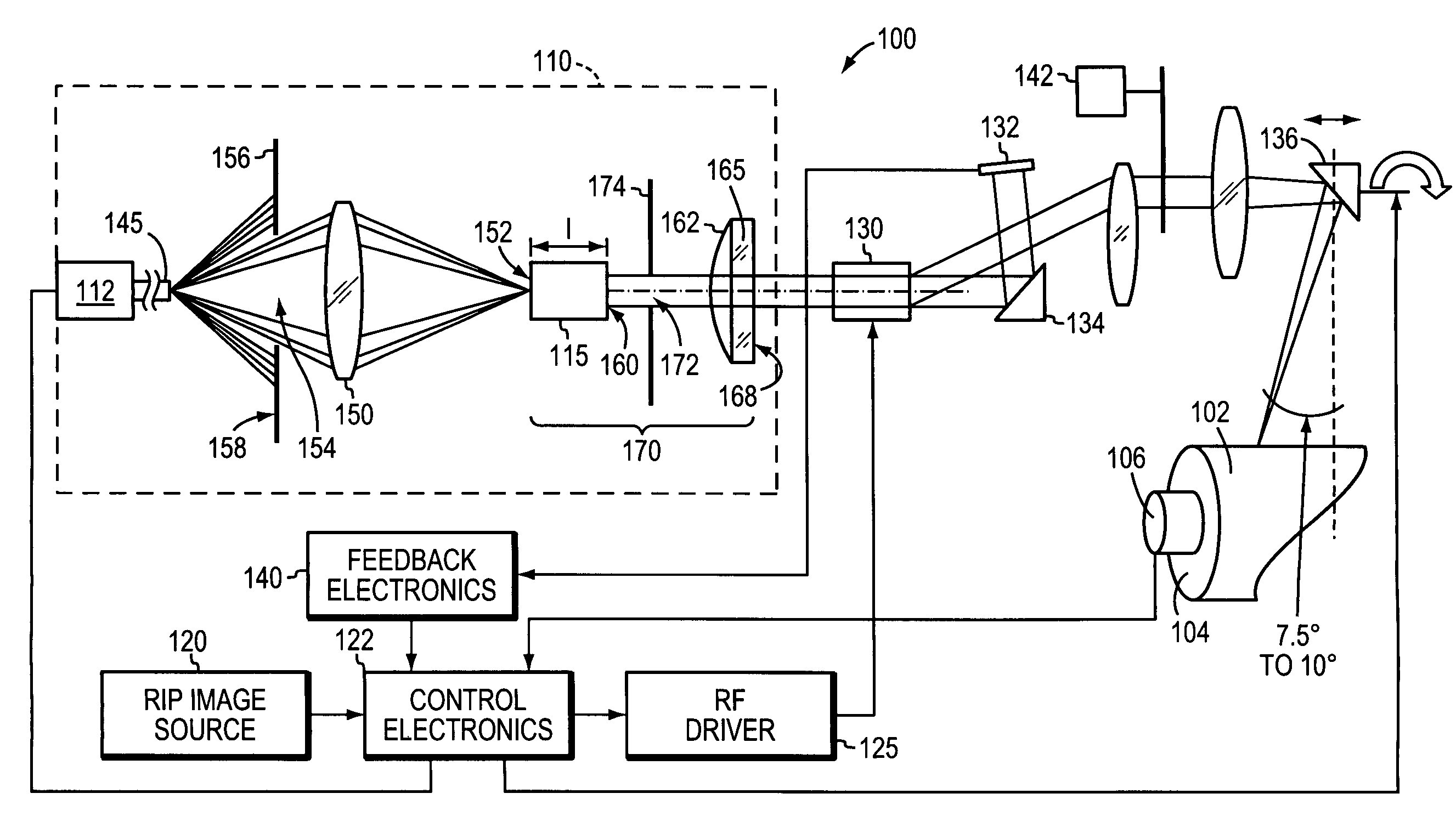
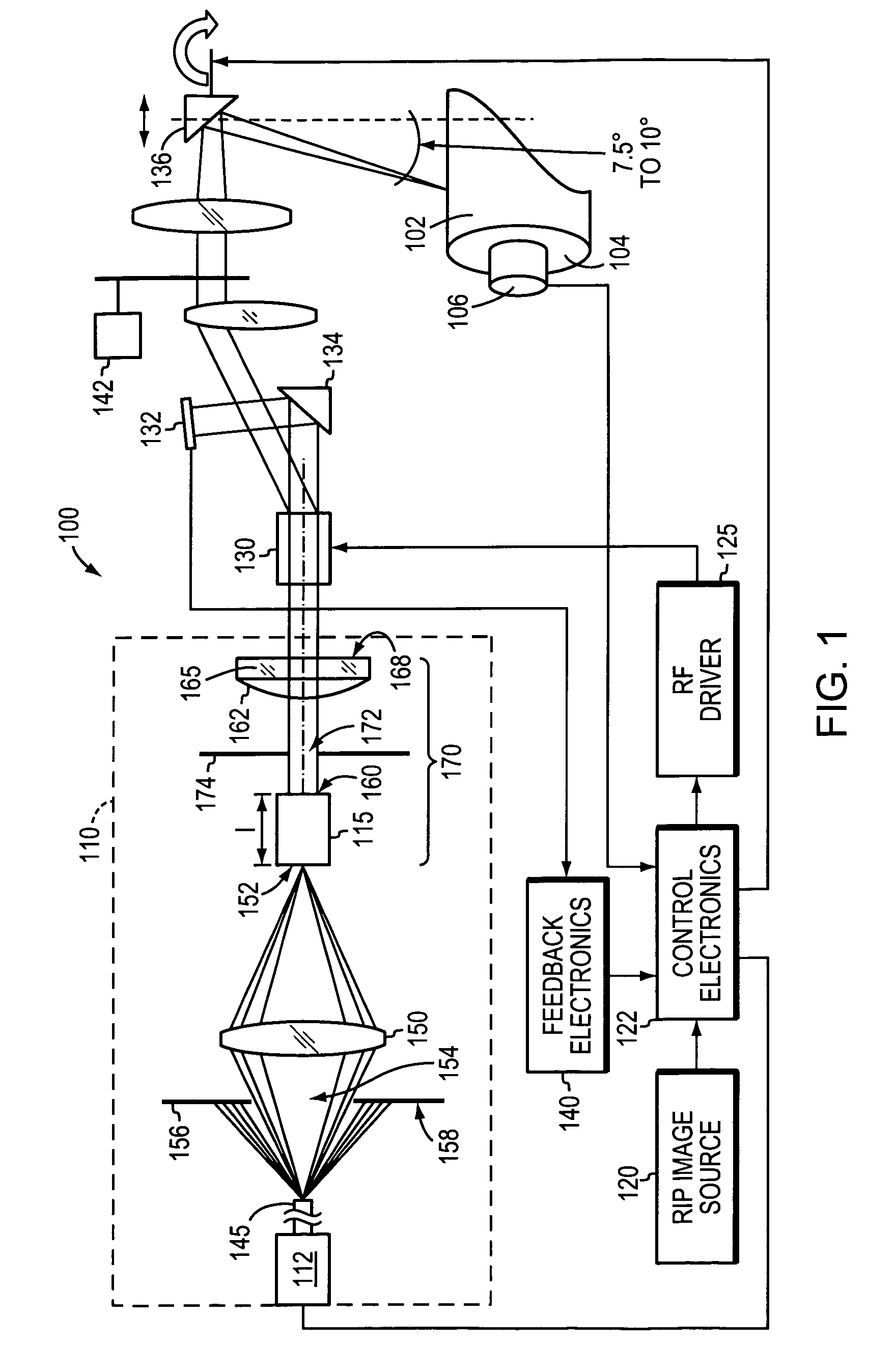
[0026]In one illustrati...


PUM

PropertyMeasurementUnit
diameteraaaaaaaaaa
diameteraaaaaaaaaa
lengthaaaaaaaaaa

Abstract

Cavity lasers exhibit a relatively high beam quality (e.g., M2<1.25) despite a relatively small cavity length (e.g., 50-53 mm) for a high (e.g., ≧10 watt) output power device. This enables the construction of physically smaller laser and optical assemblies without sacrificing performance. Reduction of optical photonic interference, which can impair imaging performance, is also facilitated. Laser and optical assemblies may utilize an aperture defined within an optical barrier element to reduce the divergence of the light beam emanating from a diode-pumping laser.

Description

CROSS-REFERENCE TO RELATED APPLICATION[0001]The present application claims priority to and the benefit of U.S. provisional application Ser. No. 60 / 568,343, filed on May 5, 2004, the disclosure of which being incorporated by reference herein.FIELD OF THE INVENTION[0002]The present invention relates generally to graphic-art imaging and more particularly to cavity laser optimizations used in lithographic imaging.BACKGROUND OF THE INVENTION[0003]In offset lithography, a printable image is present on a printing member as a pattern of ink-accepting (oleophilic) and ink-repellent (oleophobic) surface areas. Once applied to these areas, ink can be efficiently transferred to a recording medium in an imagewise pattern with substantial fidelity. Dry printing systems utilize printing members whose ink-repellent portions are sufficiently phobic to ink as to permit its direct application. Ink applied uniformly to the printing member is transferred to the recording medium in the imagewise pattern....

Claims


Application Information

Patent Timeline
Patent Type & Authority Patents(United States)
IPC IPC(8): B41J2/45H01S3/08B23K26/36B41N3/00G03F7/20H01S3/00H01S3/06H01S3/0941H01S3/16
CPCB23K26/36H01S3/005H01S3/0071H01S3/0602H01S3/09415H01S3/1611
Inventor SOUSA, JOHN GARY
Owner MARK ANDY
Why Eureka
Try Eureka