

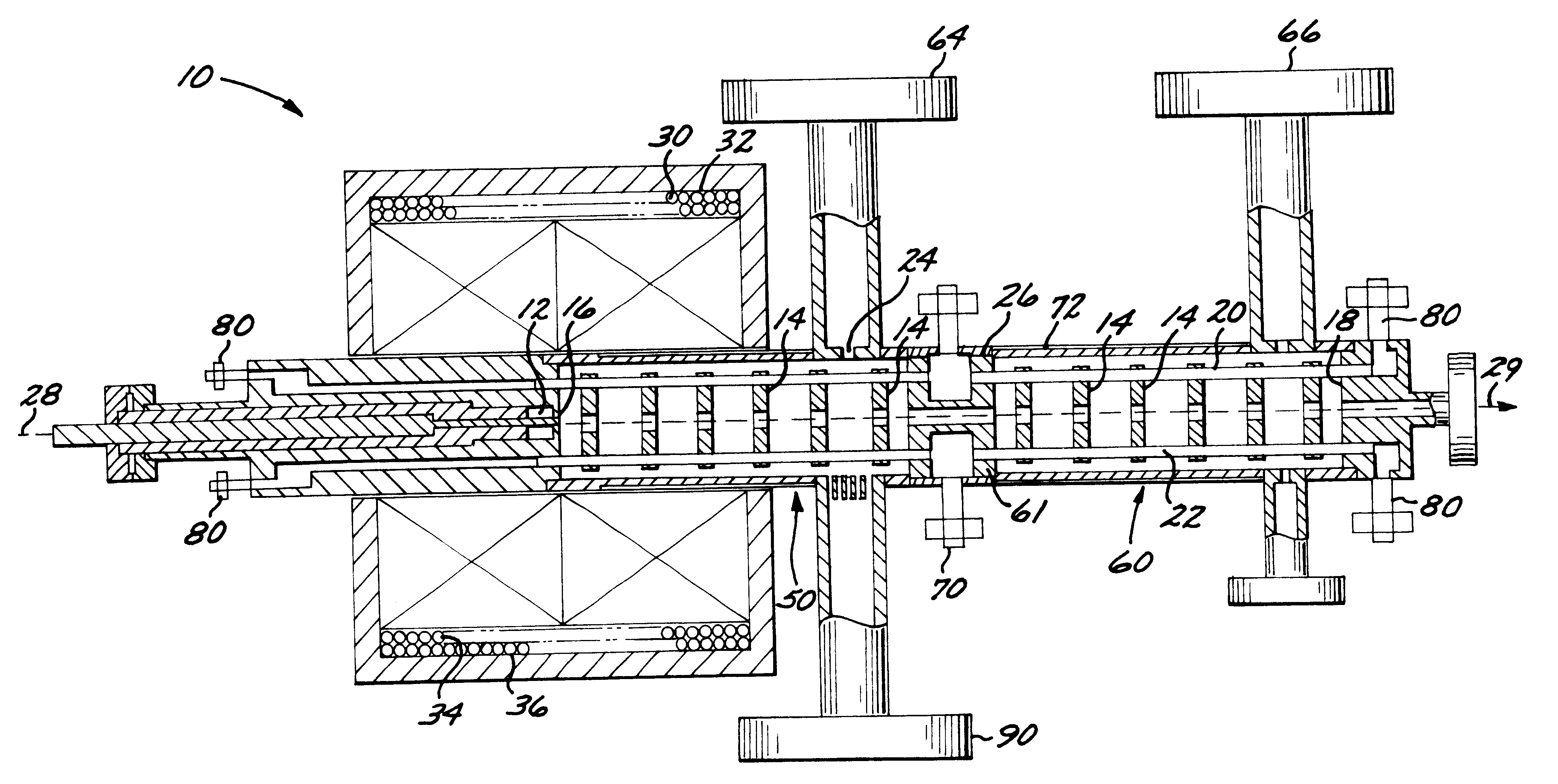
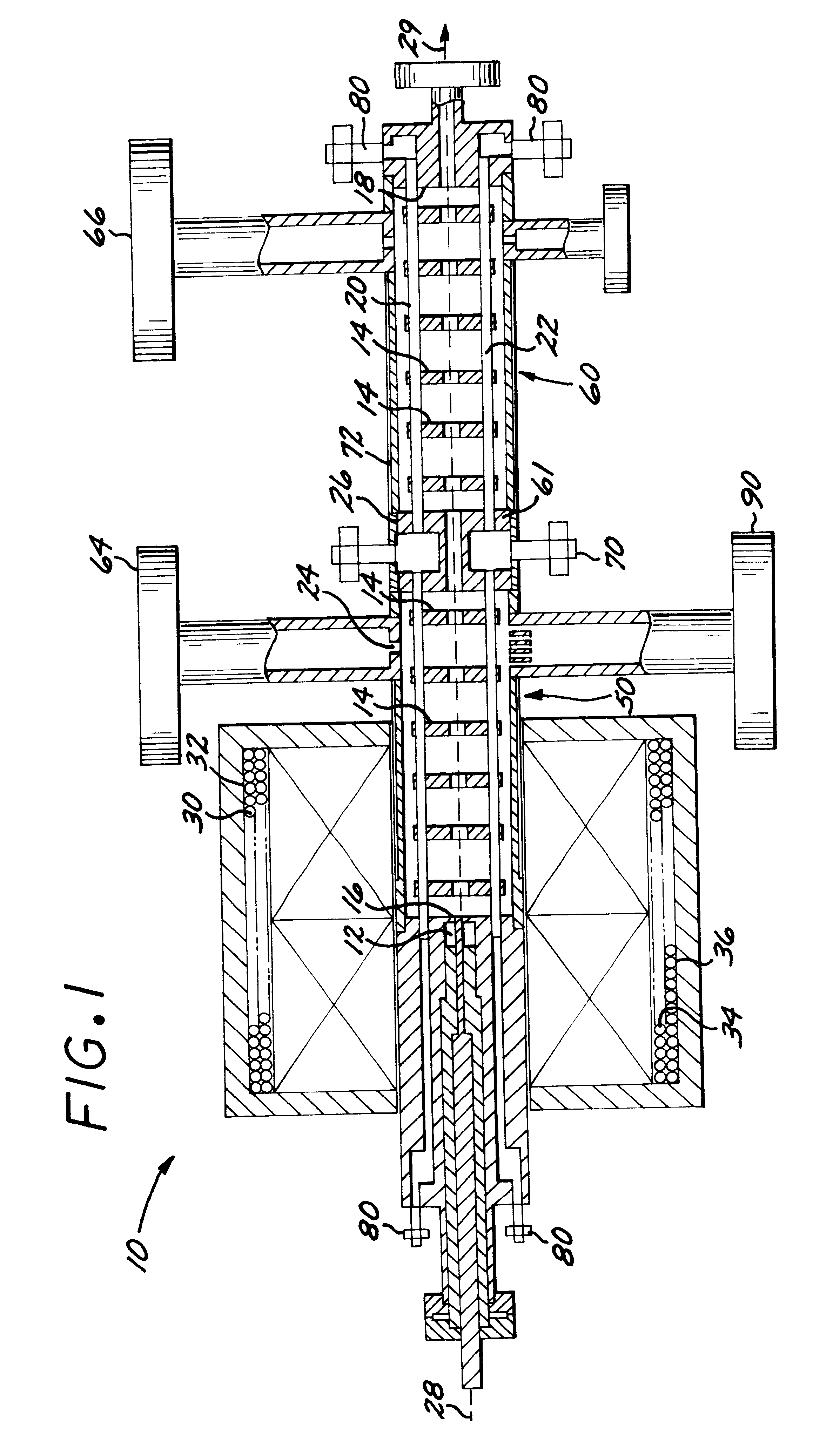
Permanent magnet focused X-band photoinjector
- Summary
- Abstract
- Description
- Claims
- Application Information
AI Technical Summary
Benefits of technology
Problems solved by technology
Method used
Image

Examples
Embodiment Construction
A higher-frequency photoelectron linac enhances a beam brightness in a much smaller footprint, important for commercial as well as high energy physics applications. For a given energy gain, the physics of frequency scaling of photoinjectors is that longitudinal and transverse beam sizes, beam charge and the cavity dimensions scale inversely with the rf frequency, while the focusing field and the accelerating gradient scale linearly. Under these scaling rules, it is expected that the emittance will also scale inversely with the rf frequency, while the current is independent of frequency. Thus, for applications demanding very high brightness electron beams, high rf frequency photoinjector sources are desired. The design of a higher-frequency, smaller photoelectron linac, poses many practical challenges. In particular, several mechanical (cooling, support), materials (breakdown, dark current) and power (magnet, klystron) issues, which do not scale simply with frequency, require design ...
PUM
 Abstract
Description
Claims
Application Information