Extended expander cycle system

a cycle system and expansion technology, applied in the field of rocket engine and combustion cycle, can solve the problems of cycle scaling, increased heat absorbed by the unit of fuel, and insufficient energy of the fuel used to cool the nozzle to drive the turbine, etc., to achieve high thrust and durability, high combustion chamber pressure, and high flow rate of fuel

Active Publication Date: 2019-03-07
BAGAVEYEV NADIR T
View PDF0 Cites 0 Cited by
  • Summary
  • Abstract
  • Description
  • Claims
  • Application Information

AI Technical Summary

Benefits of technology

[0022]In some embodiments, the extended expander cycle rocket engines use regenerative cooling to achieve both high thrust and durability. The engine's combustion chamber walls and engine nozzle walls are cooled by uncombusted fuel fed by a turbopump into a jacket or sleeve surrounding the chamber and nozzle. The fuel coming from the sleeve is cycled through the turbine side of the turbopump to serve as the driving medium for the pump. The expanded fuel emerging from the turbine side of the pump then passes into the combustion chamber injector for combustion with oxidizer in the combustion chamber. The cycle thus cools the walls of the combustion chamber and nozzle while converting a portion of the heat generated by the engine to a higher flow rate of fuel to the combustion chamber and hence a higher pressure the combustion chamber. The rest of the heat is used to preheat the fuel prior to having the fuel received by the engine's combustion chamber injector.
[0023]In industry today, when heat exchange occurs only at the boundary or outer layer or in cooling sleeves external to the engine, the amount of energy that can be acquired by the fuel on the coolant side is limited because of the limited surface area and the fact that excessive heat flux in the chamber can result in chamber failure. The present disclosure solves this limitation by implementing a plurality of heating and cooling channels throughout the engine and in various positions thereby increasing that surface area.
[0024]The most efficient heat exchange structures are those that provide the closest contact between the medium to be cooled and the coolant, i.e., the thinnest separating walls and the narrowest flow channels which provide the greatest surface area for heat transfer. Here, thanks to a 3D printed structure, the channels are within the engine and on the engine walls all built in one component rather than having channels as a separate element from the engine structure. This 3D printed design allows for the most efficient heat exchange in an expander cycle.

Problems solved by technology

However, this cycle has a problem with scaling.
Therefore, in regular Expander cycles, as the nozzle gets bigger, the heat absorbed by unit of fuel increases, and the fuel used to cool the nozzle is not energetic enough to drive the turbine.
In addition, other expander cycles and combustion cycles are limiting to the amount of heat that can be generated and limiting to the amount of energy for fuel and oxidizer pressurization.

Method used


Image

  • Extended expander cycle system
  • Extended expander cycle system
  • Extended expander cycle system

Examples


Embodiment Construction

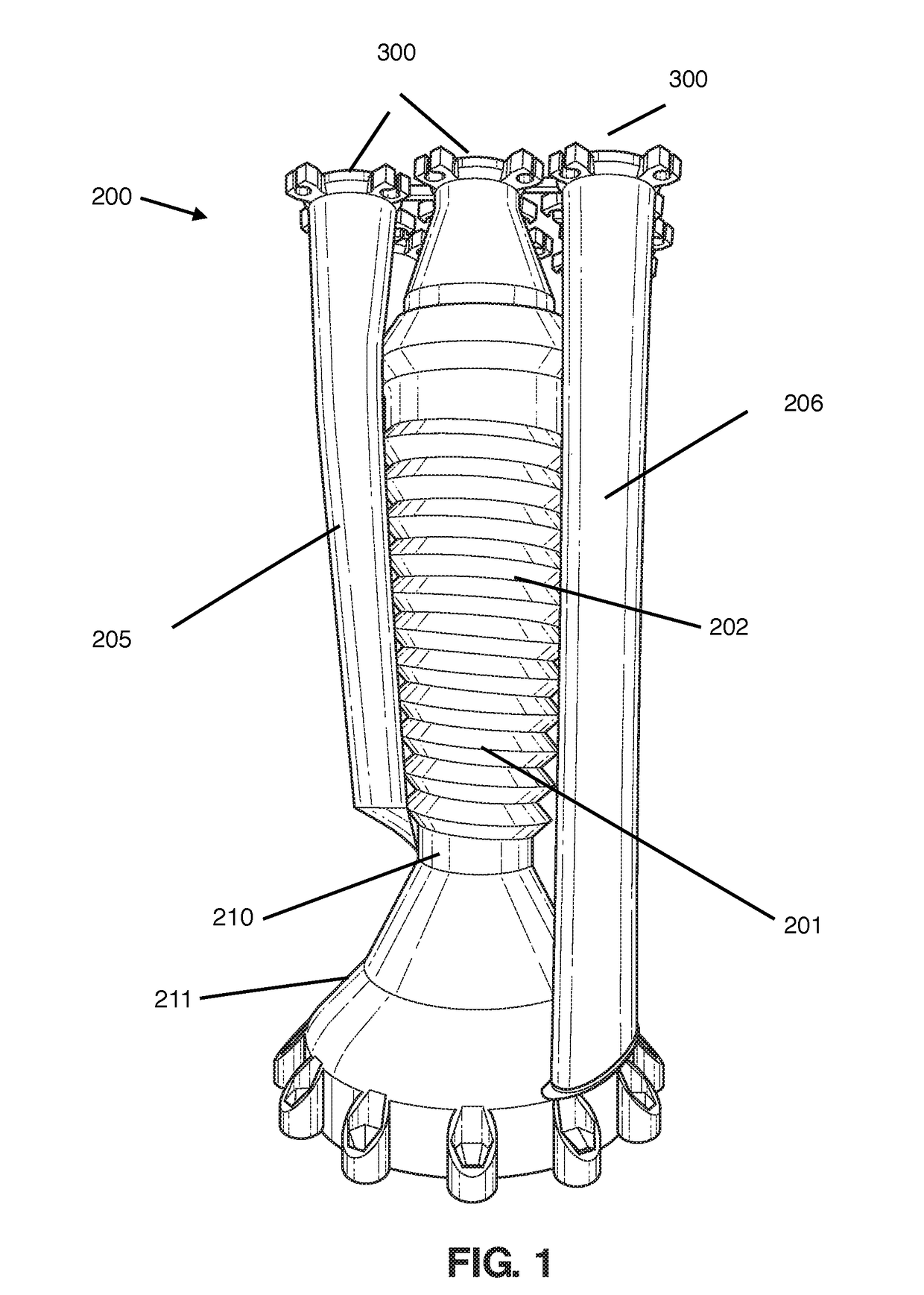
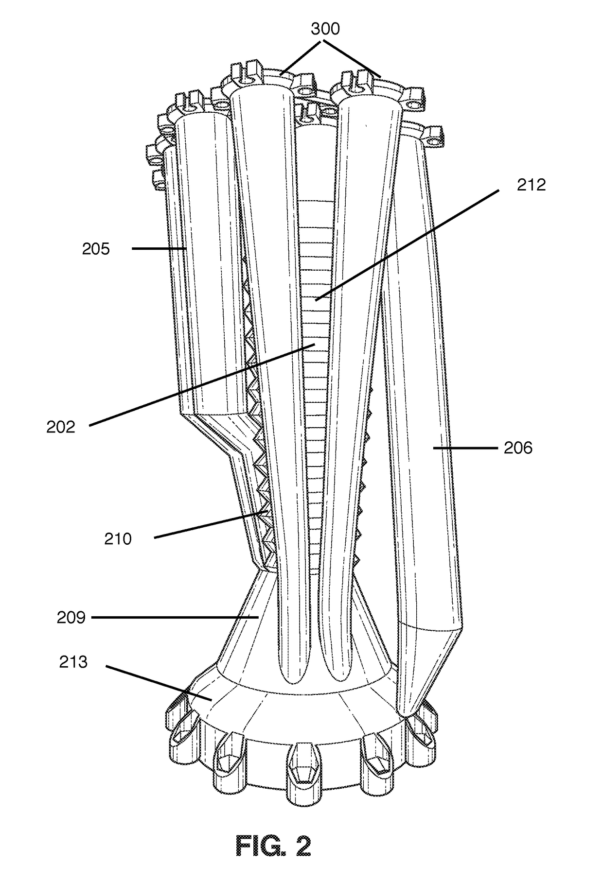
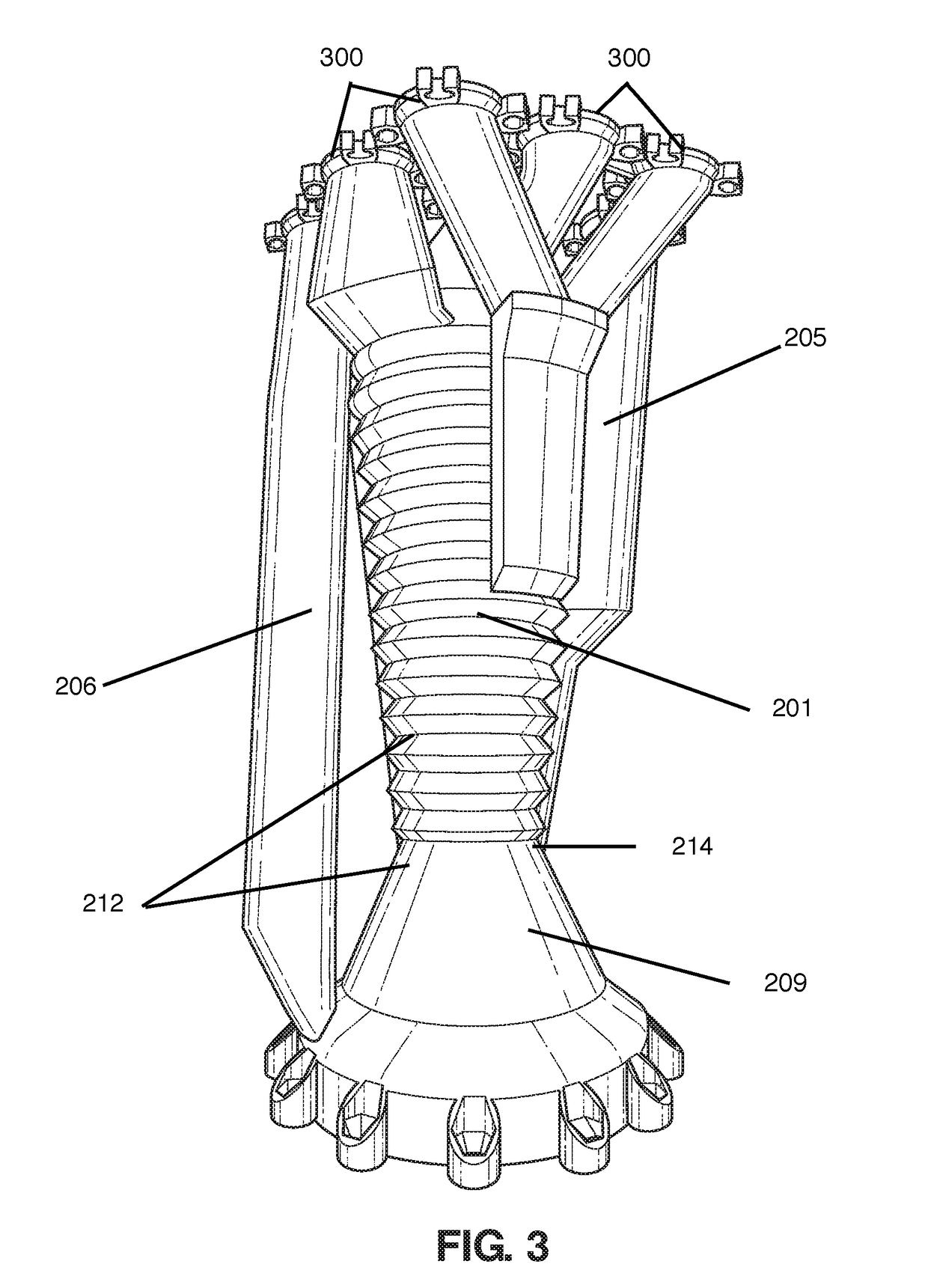
[0033]Referring now to the drawings and the characters of reference marked thereon, FIGS. 1, 2 and 3 depict an embodiment of a rocket engine 200 and one-wheel turbopumps 300 according to the present disclosure. In FIG. 1, the rocket engine 200 includes a plurality of heating and cooling channels 201, one-wheel-turbopumps 300 disposed at the top of the rocket engine, an oxidizer inlet and outlet 205, a cooling sleeve 206. Coiled channels are disposed on the rocket engine outer surface. While this embodiment shows the one-wheel-turbopumps at the top of the rocket engine, in other embodiments the one-wheel turbopumps are placed on the sides of the rocket engines and in yet another embodiment, the one-wheel turbopumps are placed on top of the rocket engine and along the sides of the engine. The one-wheel turbopumps 300 on the side of the rocket engine 200 provide a more compact design than having the one-wheel turbopumps at the top of the rocket engine, while the one-wheel turbopumps on...


PUM


Abstract

An extended expander cycle system comprising a rocket engine having a plurality of channels; a plurality of fuel supplied one-wheel-turbopumps; a plurality of oxidizer supplied one-wheel-turbopumps; wherein utilization of the plurality of channels for both fuel and oxidizer and utilization of plurality of fuel and oxidizer supplied one-wheel-turbopumps provides adequate energy for fuel and oxidizer pressurization.

Description

CROSS REFERENCE TO RELATED APPLICATIONS[0001]The present application claims benefit of U.S. Provisional Application. No. 62 / 553,785 filed Sep. 1, 2017, titled EXTENDED EXPANDER CYCLE SYSTEM.[0002]The entire content of 62 / 553,785 is hereby incorporated by reference.COPYRIGHT NOTICE[0003]A portion of the disclosure of this patent document contains material that is subject to copyright protection. The copyright owner has no objection to the facsimile reproduction by anyone of the patent document or the patent disclosure, as it appears in the Patent and Trademark Office patent files or records, but otherwise reserves all copyright rights whatsoever.BACKGROUND OF THE INVENTION1. Field of the Invention[0004]The present disclosure relates generally to rocket engines and combustion cycles in general and more particularly to an extended expander cycle system including a one-wheel turbopump and a plurality of channels which provides adequate energy for fuel and oxidizer pressurization and all...

Claims


Application Information

Patent Timeline
Patent Type & Authority Applications(United States)
IPC IPC(8): F02K9/48F02K9/64
CPCF02K9/48F02K9/64F02C7/22F02C7/222F02C7/224F02K9/46
Inventor BAGAVEYEV, NADIR T.
Owner BAGAVEYEV NADIR T
Why Eureka
Try Eureka