Lens driving device, autofocus camera and camera-equipped mobile terminal

Active Publication Date: 2011-11-24
NEW SHICOH MOTOR CO LTD
View PDF9 Cites 40 Cited by
  • Summary
  • Abstract
  • Description
  • Claims
  • Application Information

AI Technical Summary

Benefits of technology

[0028]Moreover, according to the first aspect of the invention, the magnets simultaneously serve for moving in the optical axis direction and for moving in the X-Y direction, and it is possible to move the lens support in the optical axis direction and in the X-Y direction with a first coil, at least two second coils, and at least two magnets, thus it is possible to carry out focusing movement and image stabilization movement of the lens support with a simple constitution and a small number of

Problems solved by technology

Further, even though it was possible to move the lens support in the optical axis direction using the technique of Patent Publication 1, it is possible to move only in the X

Method used


Image

  • Lens driving device, autofocus camera and camera-equipped mobile terminal
  • Lens driving device, autofocus camera and camera-equipped mobile terminal
  • Lens driving device, autofocus camera and camera-equipped mobile terminal

Examples


first embodiment

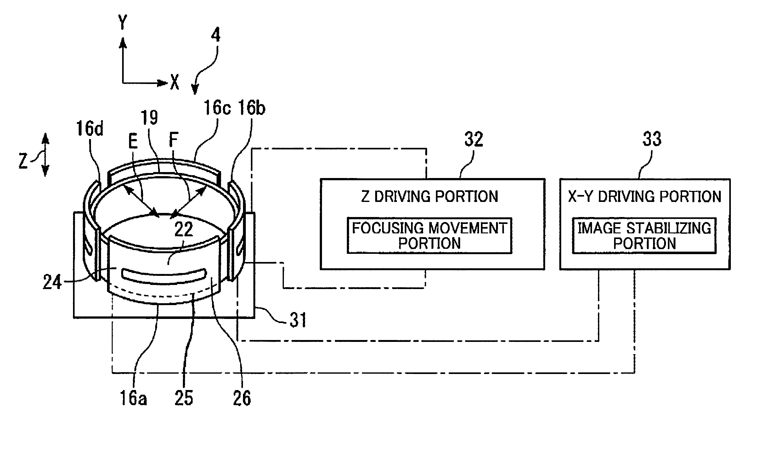
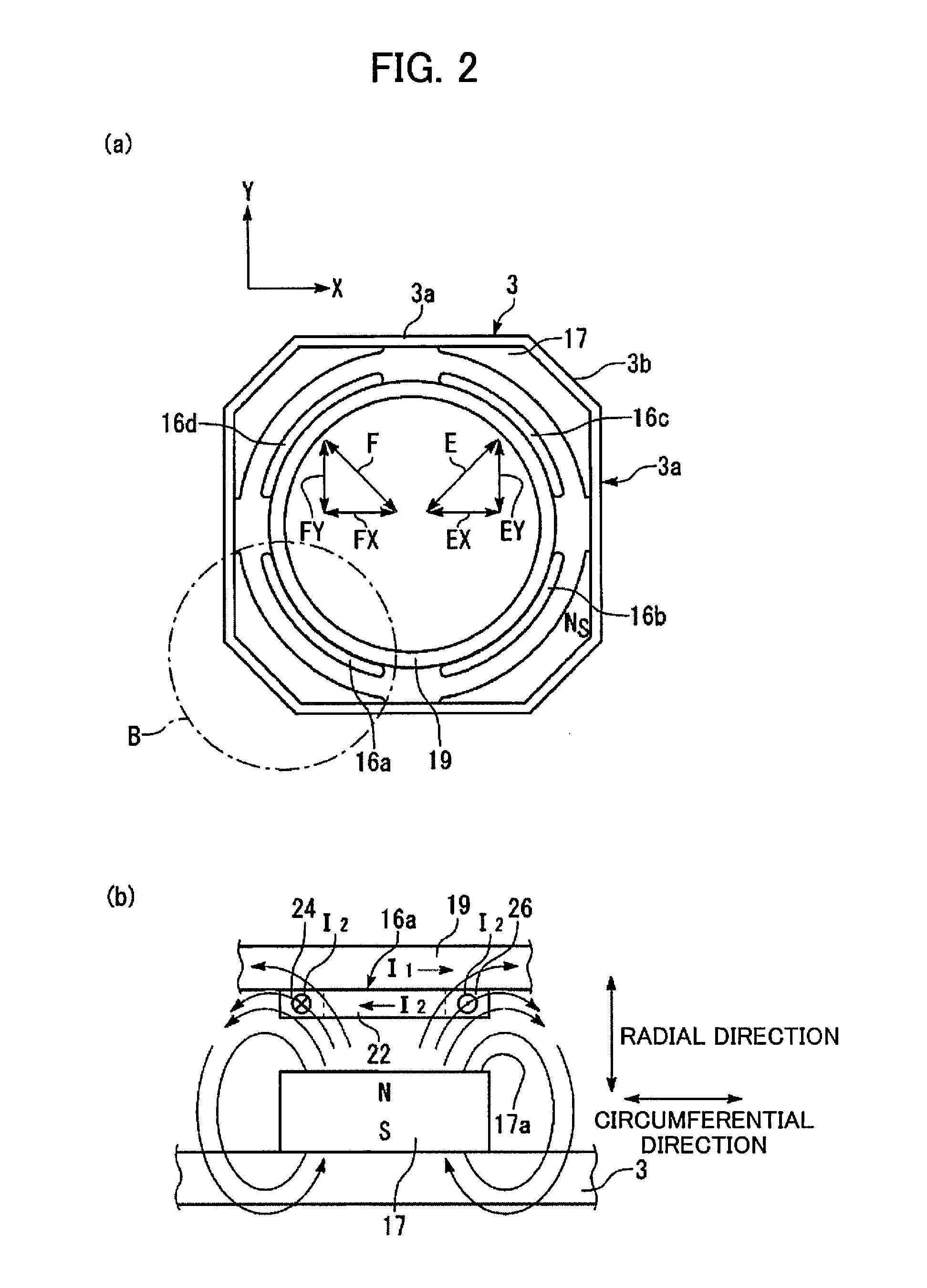
[0097]Further, as shown in FIGS. 10 and 11, at the second coils 16a to 16d, at the left and right side area portions 24 and 26, in the same way as in the first embodiment, a magnetic flux which curves further in the right and left directions further away from the inner circumferential face 17a of the magnets 17 operates, thus a thrust which moves the lens support 5 in the X-Y direction is generated. In the same way, a thrust which moves the lens support 5 in the X-Y direction also arises at the rear side area portion 25.

[0098]The present invention is not limited to the above-described embodiments, and many modifications are possible within a scope that does not deviate from the gist of the present invention. For example, the first embodiment is not limited to providing the second coils 16a to 16d and the magnets 17 at the corner portions 3b of the yoke, provided that they are at 90 degree intervals with respect to each other in the circumferential direction.

[0099]The first embodimen...

third embodiment

[0103]In the third embodiment, the inner circumferential side wall 3c, as shown in FIG. 12 and FIG. 13, may be provided continuously along the circumferential direction.

[0104]In the embodiments described above, the lens driving device 1 may be provided with a zoom lens, and the zooming function may be combined therewith.

[0105]In the third embodiment, as shown in FIG. 14, the first coil 19 is formed with an approximately square shape when seen from the front side, the second coils 16a to 16d may be disposed at sides of the first coil 19, and four of the magnets 17 are disposed at sides of the square yoke 3. In this case, as the thrust directions of the second coils 16a to 16d are X or Y, control is not needed making the sum of each of the force components EX+FX and EY+FY.

[0106]In the modified embodiment as shown in FIG. 15, as like the third embodiment, inner circumferential side wall 3c is provided opposite to side of yoke 3.


PUM


Abstract

In the lens driving device of the present invention, at least two second coils are disposed at a 90 degree interval in a circumferential direction of a first coil wound around an outer circumference of a lens support in the circumferential direction, at least four magnets are provided at an inner circumferential side of a circumferential wall of a yoke and are provided at even intervals about the circumferential direction of the first coil, each magnet being provided so that an inner circumferential face is the same magnetic pole and opposes an outer circumferential face of the first coil, and in addition is opposite the second coil at the position of providing the second coil. When the lens support is moved in the optical axis direction, an electric current flows in the first coil, and when the lens support is moved in an X-Y direction orthogonal to the optical axis, a predetermined electric current flows in a predetermined second coil.

Description

[0001]This application is based on and claims the benefit of priority from Japanese Patent Application Nos. 2010-118659 and 2010-261015, respectively filed on 24 May 2010 and 24 Nov. 2010, the contents of which are incorporated herein by reference.BACKGROUND OF THE INVENTION[0002]1. Field of the Invention[0003]The present invention relates to a lens driving device for moving a lens in an optical axis direction, to an autofocus camera provided with this lens driving device, and to a camera-equipped mobile terminal provided with this autofocus camera.[0004]2. Related Art[0005]Patent Publication 1 (Japanese Unexamined Publication No. 2002-373435) discloses that, in an actuator for an optical pickup, a lens support is moved in an optical axis direction (focus direction) and tracking direction (X direction) by providing a first coil and a second coil at a 90 degree interval in the circumferential direction of the outer circumferential face of the lens support body, disposing magnets faci...

Claims


Application Information

Patent Timeline
IPC IPC(8): G02B27/64G02B7/04
CPCG02B7/023G02B7/08G03B3/10G03B2205/0069H02K41/0356G03B2205/0015G03B5/02
Inventor SHIRAKI, MANABUICHIKAWA, KAZUHIRO
Owner NEW SHICOH MOTOR CO LTD
Why Eureka
Try Eureka