Power outputting device and vehicle mounting it, control method, storing medium and program for the power outputting device, drive device and vehicle mounting it, and, control method, storing medium and program for the drive device

a technology of power outputting device and vehicle, which is applied in the direction of dynamo-electric motor/converter starter, electric energy management, conversion with intermediate conversion to dc, etc., can solve the problems of increasing the internal resistance of slowing down the rate of chemical reaction inside the direct-current power source, and electric motors not being driven with a desired outpu

Inactive Publication Date: 2006-10-10
TOYOTA JIDOSHA KK
View PDF26 Cites 36 Cited by
  • Summary
  • Abstract
  • Description
  • Claims
  • Application Information

AI Technical Summary

Benefits of technology

[0089]In the control method of the drive unit according to the present invention, because switching control of the switching elements is carried out based on a temperature of the power source or a temperature of the DC—DC converter, so as to control the temperature of the corresponding member, it is possible to more appropriately maintain the temperature of the power source or of the DC—DC converter such that a device with simple constitution can enable the drive unit to perform to its full potential.
[0090]Such a control method of the drive unit according to the present invention can be characterized such that, based on a temperature of the power source or temperatures of the switching elements, a charged voltage of an electric storage voltage which is included in the drive unit and is capable of storing power outputted from the DC—DC converter is controlled by switching control. As described above, by controlling the charged voltage of the electric storage voltage, it is possible to maintain more appropriate conditions for the temperature of the power source or the temperature of the DC—DC converter.
[0091]Further, a control method of the drive unit according to the present invention can be characterized in that, based on a temperature of the power source or a temperature of the DC—DC converter, a switching frequency of the switching elements is set and switching control is carried out at the switching frequency set. As described above, by controlling the setting of the switching frequency of the switching elements of the DC—DC converter, it is possible to maintain more appropriate conditions for the temperature of the power source or the temperature of the DC—DC converter.

Problems solved by technology

However, in such a power plant, there are situations where the electric motor cannot be driven with a desired output because, although the power plant can operate at full performance when the direct-current power source has a normal temperature, when the temperature of the direct-current power source is low, such as at a start-up time of the electric motor, the rate of chemical reaction inside the direct-current power source slow down then internal resistance of the direct-current power source increases.

Method used


Image

  • Power outputting device and vehicle mounting it, control method, storing medium and program for the power outputting device, drive device and vehicle mounting it, and, control method, storing medium and program for the drive device
  • Power outputting device and vehicle mounting it, control method, storing medium and program for the power outputting device, drive device and vehicle mounting it, and, control method, storing medium and program for the drive device
  • Power outputting device and vehicle mounting it, control method, storing medium and program for the power outputting device, drive device and vehicle mounting it, and, control method, storing medium and program for the drive device

Examples


first embodiment

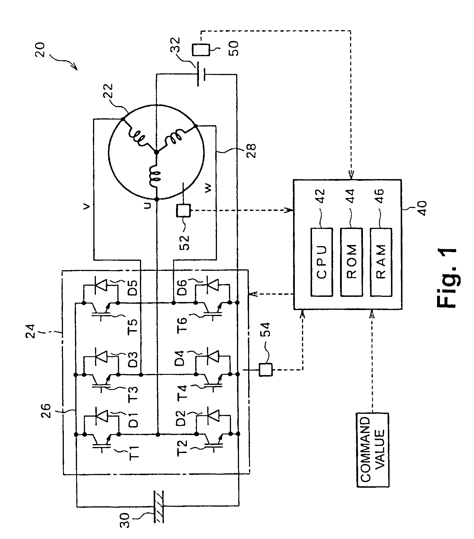
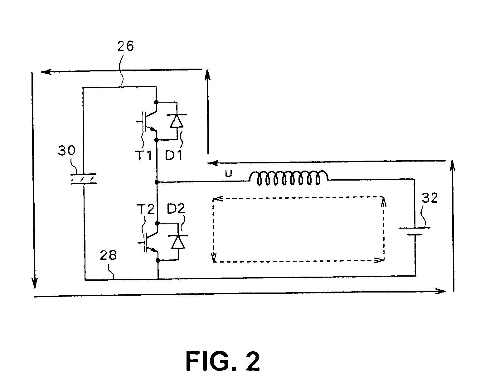
[0117]FIG. 1 is a block diagram showing an outline of outlining the constitution of a power plant 20 according to a first embodiment of the present invention. The power plant 20 according to the first embodiment comprises a motor 22 which operates by a three-phase alternating current; an inverter circuit 24 capable of converting direct electric power into three-phase alternating current power and supplying the power converted to the motor 22; a capacitor 30 which is connected with a positive electrode bus 26 and a negative electrode bus 28 of the inverter circuit 24; a direct-current power source 32 which is connected with a neutral point of the motor 22 and the negative electrode bus 28 of the inverter circuit 24; a temperature capacitor 50 for detecting a temperature of the direct-current power source 32; and an electronic control unit 40 which controls the whole device.

[0118]The motor 22 is, for example, a synchronous generator motor capable of generating electricity and comprisi...

second embodiment

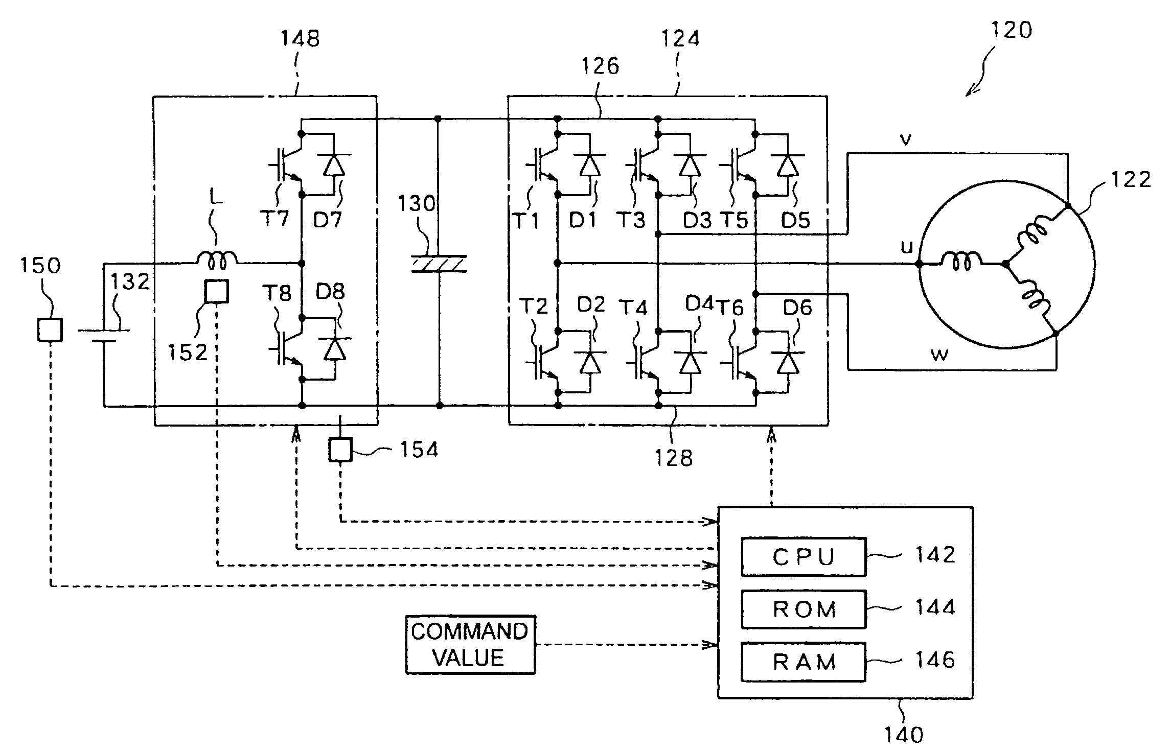
[0138]Next, a power plant 120 according to a second embodiment of the present invention will be described. FIG. 1 is a block diagram showing an outline of the constitution of the power plant 120 according to the second embodiment. As shown in FIG. 11, the power plant 120 according to the second embodiment has the same constitution as that of the power plant 20 according to the first embodiment except that a DC—DC converter 148 which carries out step-up and step-down operation is provided instead of causing the coil of each phase of the motor 22 and the transistors T1 to T6 and the diodes D1 to D6 of the inverter circuit 24 in the power plant 20 according to the first embodiment to function as the step-up and step-down chopper circuit. More specifically, the power plant 120 according to the second embodiment comprises a motor 122 which drives by a three-phase alternating current; an inverter circuit 124 which is capable of converting a electric current power into three-phase alternat...


PUM


Abstract

A power plant outputs motive power by driving a motor (22) using electric power from a direct-current power source (32). When the direct-current power source (32) has a low temperature, the direct-current power source is rapidly heated, whereby the performance can fully be demonstrated. In the power plant in which a capacitor (30) is installed so as to connect a positive electrode bus (26) and a negative electrode bus (28) of an inverter circuit (24) and the direct-current power source (32) is also installed so as to connect the negative electrode bus (28) of the inverter circuit (24) and a neutral point of the motor (22), when a power source temperature (Tb) of the direct-current power source (32) detected by a temperature sensor (50) is less than or equal to a threshold temperature (Tblow) at which supply of required electric power to the motor (22) is possible, an electronic control unit (40) sets a voltage between terminals of the capacitor (30) higher than normal and also sets a frequency of a carrier wave lower than normal, and performs switching control of transistors (T1 to T6) Thus, a ripple of a neutral point current which flows into the direct-current power source (32) can be increased, whereby it is possible to promote calorification of the direct current power source (32).

Description

TECHNICAL FIELD[0001]The present invention relates to a power plant which is capable of outputting motive power by driving an electric motor and a vehicle to mount the power plant, a control method, a storage medium, and a program of the power plant, a drive unit which is capable of driving a load and a vehicle to carry the drive unit, and a control method, a storage medium, and a program of the drive unit.BACKGROUND ART[0002]Heretofore, a conventional power plant which comprises a capacitor connected with a positive electrode bus and a negative electrode bus of an inverter circuit for supplying three-phase alternating current power to an electric motor and a direct-current power source connected with the positive electrode bus or the negative electrode bus of the inverter circuit and a neutral point of the electric motor has been proposed (for example, Japanese Patent Laid-Open Publication No. Hei 10-337047, Japanese patent Laid-Open Publication No. Hei 11-178114, and the like). In...

Claims


Application Information

Patent Timeline
Patent Type & Authority Patents(United States)
IPC IPC(8): H02M5/45B60L11/18H02M7/48H02P21/34H02P27/08
CPCB60L11/1803H02P6/08H02P27/08H02P29/0044B60L11/1861B60L11/1875B60L15/007H01M10/5006H01M10/5026B60L11/1851Y02T10/7216B60L2240/525Y02T10/7005Y02T10/705B60L2210/10B60L2240/36B60L2240/425B60L2240/545B60L2270/145H01M10/5016Y02T10/7044Y02T10/644B60L50/51B60L58/10B60L58/27H01M10/615H01M10/625H01M10/637H02P29/60Y02E60/10Y02T10/64Y02T10/70Y02T10/72H02P27/06H02P6/10
Inventor KOMATSU, MASAYUKISATO, EIJIOKI, RYOJISHAMOTO, SUMIKAZUNAKAMURA, MAKOTO
Owner TOYOTA JIDOSHA KK
Why Eureka
Try Eureka