Optical waveguide modulator with output light monitor

a technology of optical waveguide modulator and output light, which is applied in the direction of optical waveguide light guide, instruments, optics, etc., can solve the problems of increasing the cost of the modulator system, increasing the limitations of the dimension and form of the system, and reducing the reliability of the system, so as to achieve simple constitution, small limit in dimension and form, and high reliability

Inactive Publication Date: 2005-05-19
SUMITOMO OSAKA CEMENT CO LTD
View PDF13 Cites 34 Cited by
  • Summary
  • Abstract
  • Description
  • Claims
  • Application Information

AI Technical Summary

Benefits of technology

[0009] An object of the present invention is to provide an optical waveguide modulator having an output light monitor to which the limitations in dimension and form are small and which is capable of monitoring the intensity of output light from the modulator by a monitoring means having a simple constitution with high reliability and with at low cost.

Problems solved by technology

In this system, however, there is the problem that since the optical coupler for providing the monitoring branched light and the photoelectric conversion elements must be arrange outside of the modulator module, the cost of the modulator system increases, limitations on the dimension and form of the system increase and the reliability of the system decreases.
In this system, installation of a lens etc. for taking the monitoring light out of the optical waveguide element is necessary and, as the monitoring light is taken out of the optical waveguide element, a member for receiving the monitoring light must be installed on the optical waveguide element after the element is fixed in a container case, and this installation is difficult and complicated.
In this system, the inclined end form of the element must be determined to an extent such that the inclined end does not affect the main output light from the element, and thus there is a problem in practical utilizability of this system.
In this device, a means for fixing the light-receiving element must be installed on the optical waveguide element and since the fixing means-installation work, a work for connecting the fixing means to the light-receiving element and an operation for adjusting the connected light-receiving element are effected after the optical waveguide element is fixed to a container case, the above-mentioned works and operation are very difficult and the possibility of damaging the optical waveguide element by the above-mentioned works and operation is high.

Method used


Image

  • Optical waveguide modulator with output light monitor
  • Optical waveguide modulator with output light monitor
  • Optical waveguide modulator with output light monitor

Examples


Embodiment Construction

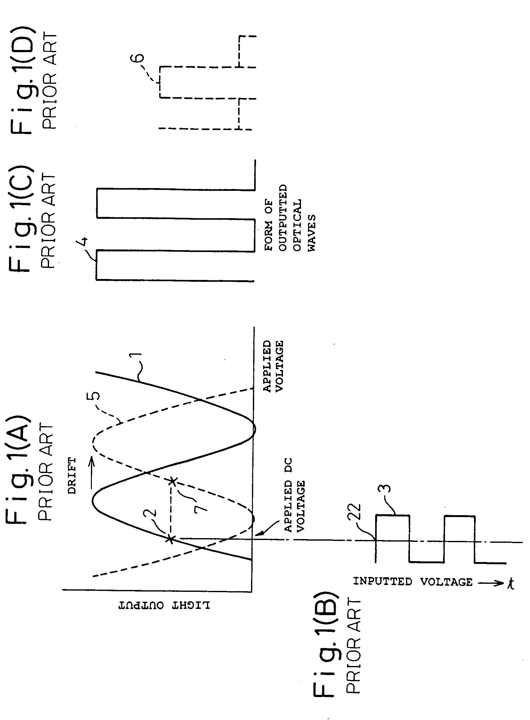
[0107] As mentioned above, in the optical waveguide modulator, usually a drift in working point voltage, which is referred to as a temperature drift and a DC drift, occurs and thus it is necessary that the working point voltage is controlled in response to the output of the modulator to retain the working point in the same one point on a particular characteristic curve even when the drift occurs. This necessity will be explained below in referring to FIGS. 1(A) to 1(D). In the form of waves 1 in the applied voltage-light output characteristic curve of a modulator, when a working point is located in a central point 2 of the wave form 1, and an RF signal 3 as shown in FIG. 1(B) is applied to the modulator through a light-inputting optical fiber 22, the resultant light output has a form of waves 4 of signal shown in FIG. 1(C) which form is analogous to that of the applied RF signal 3. In this case, when the form of waves of the characteristic curve is shifted to a form of waves 5 shown...


PUM

PropertyMeasurementUnit
radiation angleaaaaaaaaaa
outer diameteraaaaaaaaaa
phase angleaaaaaaaaaa

Abstract

An optical waveguide monitor equipped with an output light monitor having a decreased restriction in the dimensions and form thereof, a high reliability and a low production cost includes an optical waveguide element (having a plurality of surface waveguide portions, a connecting portion for converging and connecting the surface waveguide portions and an output light-outputting waveguide portion connected to the connecting portion each formed on a dielectric substrate plate; an output light optical fiber connected to an output end of the output light-outputting waveguide portion, a reinforcing capillary for reinforcing a connection between the optical waveguide element and the output light optical fiber and a monitoring light receiving means, wherein the reinforcing capillary has a hole or groove for containing and supporting the output light optical fiber therein, a connecting face thereof bonded to an output end face of the substrate, and a terminal surface opposite to the connecting face, to thereby enable at least one member of the reinforcing capillary per se and a monitoring light optical fiber located within the capillary to receive the monitoring light outputted from the optical waveguide element, to transmit it therethrough and to output it to the outside of the capillary, and the monitoring light receiving means is located in a position suitable to receive the monitoring light outputted to the outside of the reinforcing capillary and has a photoelectric conversion element.

Description

TECHNICAL FIELD [0001] The present invention relates to an optical waveguide modulator equipped with an output light monitor. More particularly, the present invention relate to an optical waveguide modulator, equipped with an output light monitor, usable for modulating an external light intensity in the optical communication field, and capable of monitoring output light by utilizing monitoring light radiated or outputted from an optical waveguide, and controlling the working point in the modulation of light intensity by feeding-back the monitoring results. BACKGROUND ART [0002] An optical waveguide modulator, in which an optical waveguide is formed on a substrate plate comprising LiNbO3 (which may be referred to as LN hereinafter) or GaAs, is advantageous in that the working velocity is high, the dependency on wavelength is low and the driving voltage is low, and thus it is widely used for practical external modulators in the optical communication field. Particularly, an optical wav...

Claims


Application Information

Patent Timeline
Patent Type & Authority Applications(United States)
IPC IPC(8): G02B6/30G02B6/42G02F1/01G02F1/21G02F1/225
CPCG02B6/30G02B6/4214G02B6/423G02B6/4246G02F1/0123G02F2203/21G02F1/225G02F1/2255G02F1/295G02F2001/212G02F2201/58G02F1/035G02F1/212
Inventor YAMADA, MANABUMIYAZAKI, NORIKAZUHARA, TOKUTAKA
Owner SUMITOMO OSAKA CEMENT CO LTD
Why Eureka
Try Eureka