Controlled radial magnetic bearing

a magnetic bearing and control technology, applied in the direction of magnetic bearings, mechanical energy handling, mechanical equipment, etc., to achieve the effect of small rotation loss, small eddy current loss, and reduced eddy curren

Inactive Publication Date: 2005-04-26
SANKYO SEIKI MFG CO LTD
View PDF5 Cites 34 Cited by
  • Summary
  • Abstract
  • Description
  • Claims
  • Application Information

AI Technical Summary

Benefits of technology

[0009]According to the present invention, the above-mentioned object is achieved by a controlled type magnetic radial bearing provided with plural electromagnet poles which are arranged at a predetermined interval in a circumferential direction of a rotary body at the same position in an axial direction of the rotary body and all of the electromagnet poles are set to be the same polarity, characterized in that the flux densities formed by the electromagnet poles are gradually changed in the circumferential direction of the rotary body. The change of the flux densities in the circumferential direction of the rotary body becomes small and smooth. As a result, the eddy current generated in the rotary body during rotation is decreased, an eddy current loss and rotation loss are reduced and extremely satisfactory rotational characteristics can be obtained with a simple constitution at low cost.
[0010]Here, “the flux densities are gradually changed” means that even if there is a difference between the maximum value of the flux density and the minimum value, the change of the flux densities between the adjacent electromagnet poles is small and smooth.

Problems solved by technology

In such a controlled type magnetic radial bearing, there is a problem caused by eddy current loss produced inside a rotary body at a high-speed rotation.
However, there have been increasing applications in recent years in which the loss of eddy current and the rotation loss due to the eddy current practically cause problems even though laminated steel plates are used for the rotor part of a rotary body in a device such as an energy-storage flywheel and an ultra high-speed rotary body.

Method used


Image

  • Controlled radial magnetic bearing
  • Controlled radial magnetic bearing
  • Controlled radial magnetic bearing

Examples


first embodiment

[0054]Next, with reference to FIG. 3, a control system for the magnetic radial bearing will be described. In FIG. 3, only the portions of the rotary body 1 and the magnetic pole 6 of the respective electromagnets M are shown.

[0055]Although detailed illustration is omitted, two x-axis-direction position sensors 12 and 13 for detecting displacement of the rotary body 1 in the x-axis direction and two y-axis-direction position sensors 14 and 15 for detecting displacement of the rotary body 1 in the y-axis direction are provided near the electromagnets M.

[0056]A controller (control means) 16 for radial direction control which controls the exciting current supplied to the coils 10 and 11 of the respective electromagnets M based on the output signal from the position sensors 12 to 15 is provided in the magnetic radial bearing. The controller 16 is provided with an x-axis-direction displacement calculating section 17 for determining a displacement of the rotary body 1 in the x-axis direct...

second embodiment

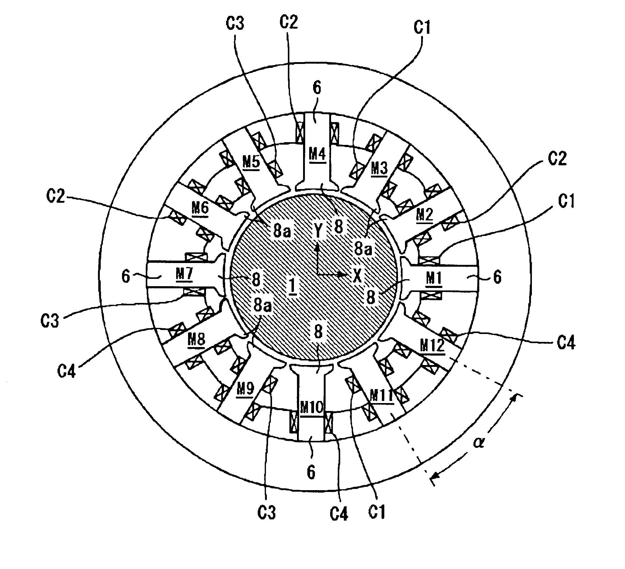
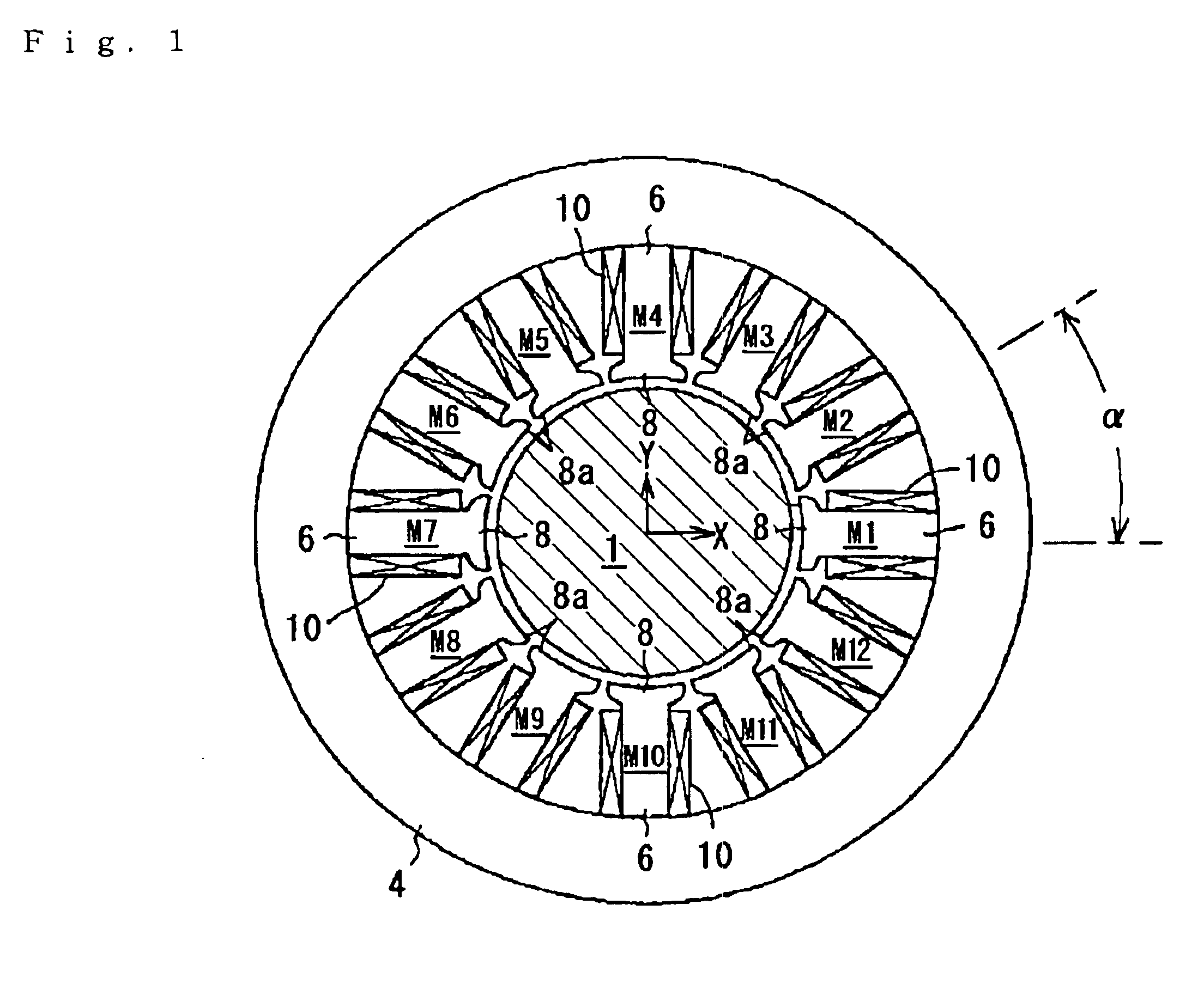
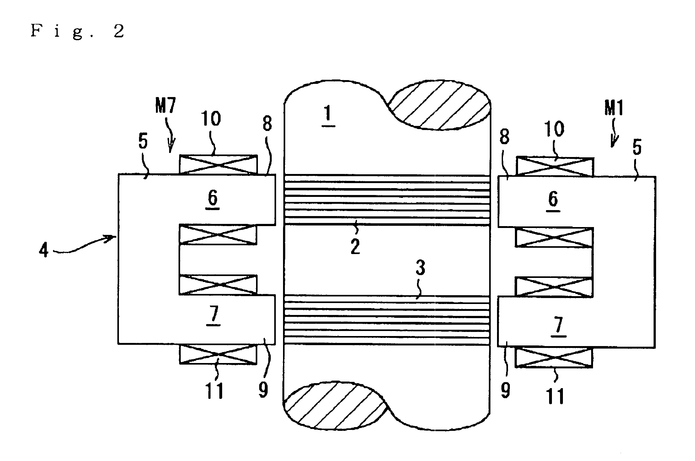
[0072]The upper magnetic radial bearing 23 is provided with twelve electromagnets (upper electromagnets) m1 to m12 arranged in a similar manner as the second embodiment described above. Each of the electromagnets “m” is equipped with a salient pole 8, around which a coil 10 is wound so as to constitute a magnetic pole 6. Each of the salient poles 8 is opposed to the outer peripheral face of an upper rotor part 2 of the rotary body 1. The lower magnetic radial bearing 24 is equipped with twelve electromagnets (lower electromagnets) m1 to m12 arranged in the similar manner as the upper electromagnets “m”. In FIG. 6, only two lower electromagnets m1 and m7 are shown. The lower electromagnets are shown generically with a notational symbol “m”. The constitution of the lower electromagnets “m” is the same as the upper electromagnets “m” and the same notational symbol is given to the same portion.

[0073]The salient pole 8 of the lower electromagnet “m” is opposed to the outer peripheral fac...

fifth embodiment

[0096]A constitution of the controller 16 is similar to the fifth embodiment except for the number of amplifiers A and a part of processing in the control section 19. The controller 16 is provided with two amplifiers A1 and A2 corresponding respectively to two groups of coils C.

[0097]In the controller 16, as similar to the second embodiment, a control section 19 calculates a control current value Ixc in an X-axis direction and a control current value Iyc in a Y-axis direction and outputs control current value signals proportional to these control current values Ixc and Iyc to the corresponding amplifiers A. The control current Ixc is supplied to the first coil C1 from the first amplifier A1 and the control current Iyc is supplied to the second coil C2 from the second amplifier A2. Thereby the control current Ixc is supplied to the first coil 1 of the first to the third electromagnets M1 to M3, the eleventh and the twelfth electromagnets M11 and M12. On the other hand, the control cu...


PUM


Abstract

The flux densities formed by plural electromagnet poles M1 to M12 which are arranged at a predetermined interval in a circumferential direction of a rotary body 1 at the same position in an axial direction of the rotary body 1 are gradually changed in the circumferential direction of the rotary body. Even if there is a difference between the maximum value of the flux density and the minimum value, the change of the flux densities between the adjacent electromagnet poles is small and smooth. Accordingly satisfactory detective sensitivity and detection results can be obtained.

Description

TECHNICAL FIELD TO WHICH THE INVENTION RELATES[0001]This invention relates to a controlled type magnetic radial bearing which supports a rotary body used for an energy-storage flywheel, an ultra high-speed rotating body or the like in a non-contact manner in a radial direction.BACKGROUND ART[0002]Controlled type magnetic bearing devices, which magnetically levitate a rotary body for supporting in a non-contact state, have been widely used in various fields in recent years since the loss accompanied by rotation can be remarkably reduced.[0003]Generally a controlled type magnetic bearing device is provided with a group of controlled type magnetic axial bearings which support a rotary body in a non-contact state in an axial direction and two groups of controlled type magnetic radial bearings which support the rotary body in a non-contact state in a radial direction. The magnetic radial bearing is equipped with plural electromagnets (usually four pieces) which are arranged at equal inte...

Claims


Application Information

Patent Timeline
Patent Type & Authority Patents(United States)
IPC IPC(8): F16C39/00F16C39/06F16C32/04
CPCF16C32/0444F16C32/0465F16C32/0485F16C32/048F16C32/0491F16C2361/55
Inventor OKADA, YOHJIKANEBAKO, HIDEKIABE, KEISUKE
Owner SANKYO SEIKI MFG CO LTD
Why Eureka
Try Eureka