
Battery pack

Inactive Publication Date: 2010-07-22
SAKAKIBARA KAZUYUKI
View PDF10 Cites 172 Cited by
  • Summary
  • Abstract
  • Description
  • Claims
  • Application Information

AI Technical Summary

Benefits of technology

[0087]There will be first described advantageous effects of an exemplary embodiment of the present invention, with respect to output performance. A cordless power tool according to an exemplary embodiment of the present invention operates such that a battery pack supplies to an AC motor an AC voltage of above 36 V, which is such as 48V, 72V or 100V, Therefore, as the output level of a cordless power tool according to an exemplary embodiment of the present invention becomes closer to the same as the commercial power source, such a cordless power tool can show increasing differences in output level from a conventional cordless power tool powered by a voltage of 14.4V or 36V.
[0088]A battery cell within a battery pack has the internal resistance, and, during discharge, consumes energy whose amount varies proportional to the square of the loading current value of the battery cell, in the form of heat emission from the battery cell. In a cordless power tool according to an exemplary embodiment of the present invention, the loading current of the cordless power tool, particularly when the toll is powered by the same as a voltage of the commercial power source, remarkably small in comparison with the loading current in a conventional cordless power tool powered by a voltage of 14.4 V or 36 V. Therefore, in a battery pack according to an exemplary embodiment of the present invention, the energy which is consumed in the form of heat emission is minor in comparison with a conventional battery pack having an output voltage of 14.4 V or 36 V.
[0089]In addition, in a battery pack according to an exemplary embodiment of the present invention, because the battery pack outputs an AC voltage having a level which is the same as the effective value of the commercial power source, discharge output terminals can be provided which are connectable with an outlet plug for use with the commercial power source . Therefore, the battery pack can be used to power even a conventional AC power tool, with its electrical cord connected with the battery pack. This battery pack would provide an effect that the battery pack can be used in an environment where a user owns and uses various types of AC power tools for various kinds of work, with the battery pack acting as a simplified auxiliary power source when the use finds it difficult to utilize the commercial power source, with an additional effect that the battery pack does not require the user to temporarily use a conventional cordless power tool which outputs power at an unsatisfactory level, for utilization of the commercial power source, which provides improved ease-to-use of power tools.
[0090]There will be described next effects of an exemplary embodiment of the present invention, with respect to a runtime. In a cordless power tool according to an exemplary embodiment of the present invention, the loading current is so remarkably small that energy which is consumed in the form of heat emission is small, in comparison with a conventional cordless power tool, with increased efficiency of power supply from the battery pack to the motor.
[0091]Therefore, in a battery pack according to an exemplary Embodiment of the present invention, the loading current required to be supplied can be reduced, such that the reduced loading current is smaller than that of a conventional battery pack, by down to the reciprocal of an output voltage ratio between the battery pack according to the invention and the conventional battery pack. That is, in a battery pack according to an exemplary embodiment of the present invention, the amount of electricity required to be supplied to the motor can be reduced relative to when a conventional battery back is used for machining the same workpiece. As a result, in a battery pack according to an exemplary embodiment of the present invention, even if the battery cell capacity is selected to be smaller than that of a conventional battery pack, by down to the reciprocal of the output voltage ratio with the conventional battery pack, the runtime can be long enough to satisfy the user.
[0092]In addition, when a required runtime exceeds a runtime which can be provided by a fully-charged battery pack, and subsequent work is needed without interruption, electrical connection of a cordless power tool according to an exemplary embodiment of the present invention with an electrical cord adapter according to an exemplary embodiment of the present invention would enable continuous work, with the cordless power tool acting as a corded AC power tool. Because the AC motor, which is powered by electricity which is directly supplied from the commercial power source, is used, a whole AC-DC converter in a conventional system can be eliminated, which would satisfy a need about an AC-DC converter.

Problems solved by technology

Conventional systems including 14.4V cordless power tool systems and 36V cordless power tool systems, however, cannot satisfy all of the user demands, because these systems have been specialized to have a system design that can satisfy only part of the user demands.

Method used


Image

  • Battery pack
  • Battery pack
  • Battery pack

Examples


Embodiment Construction

[0144]Several presently preferred embodiments of the invention will be described in more detail by reference to the drawings in which like numerals are used to indicate like elements throughout.

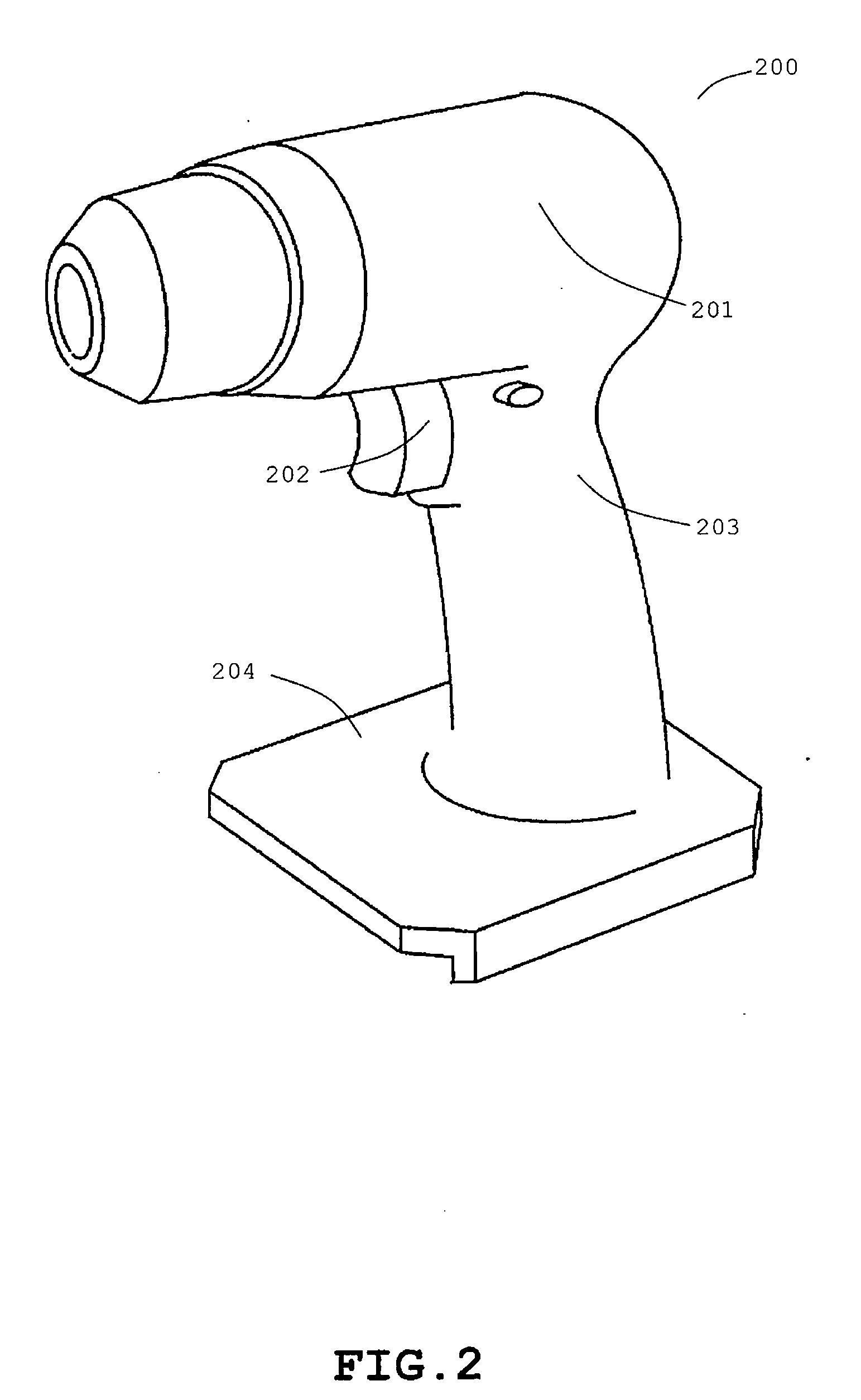
[0145]With reference to the drawings, a cordless power tool will be next described which is constructed according to an embodiment of the present invention. FIGS. 1-7 schematically illustrate the construction of a cordless power tool system, while FIGS. 8-12 schematically illustrate in block diagram how to use the cordless power tool system.

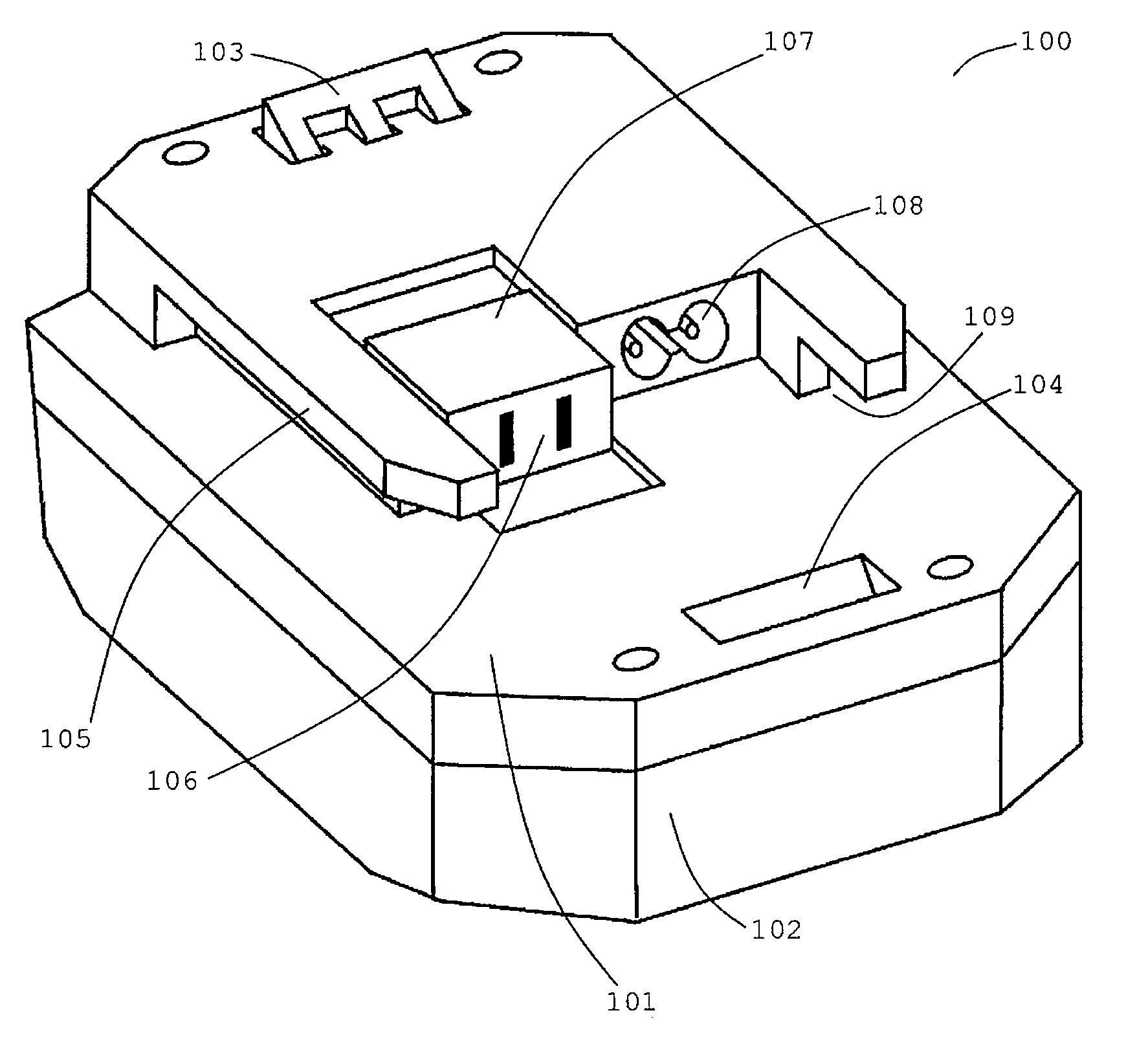
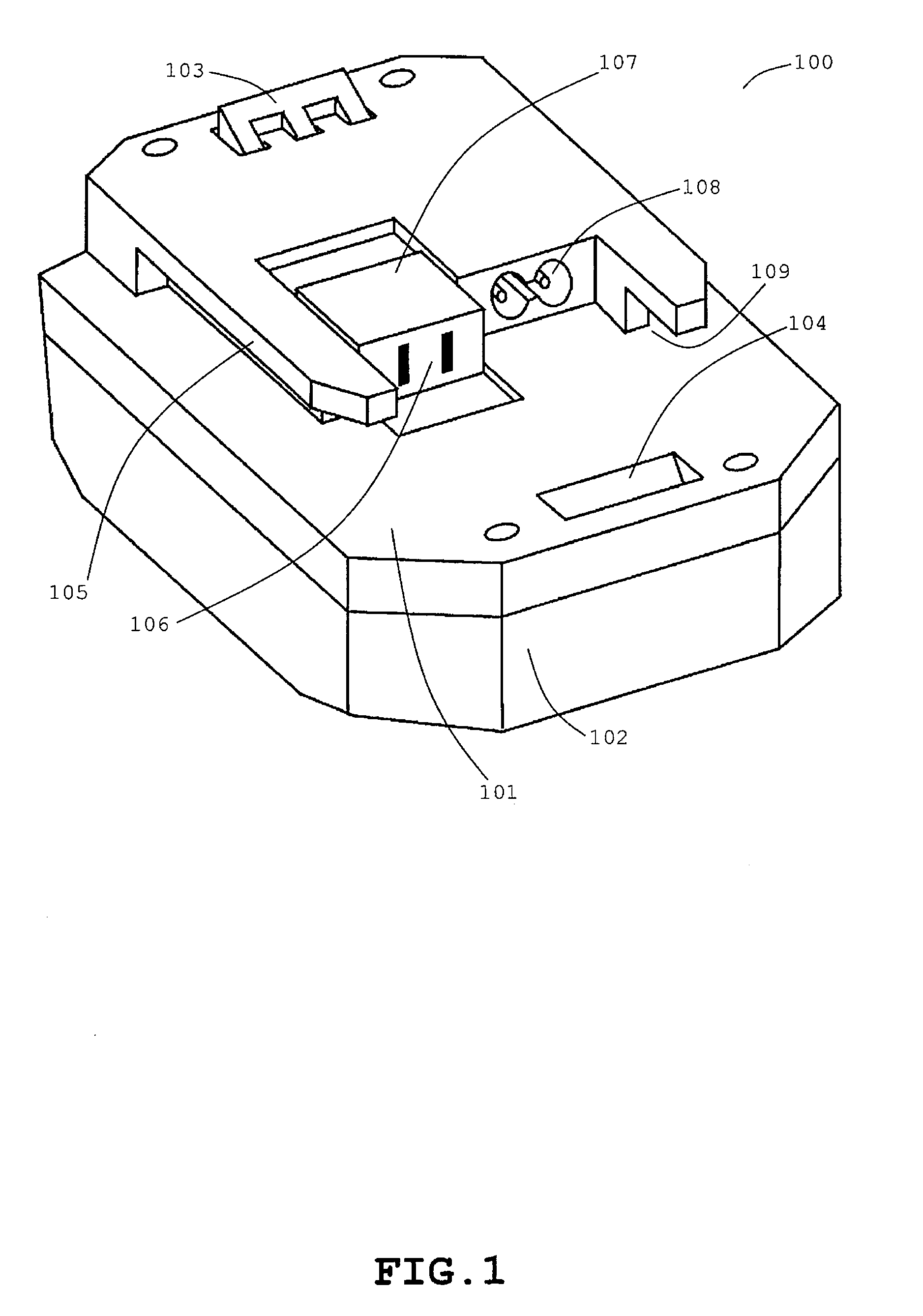
[0146]FIG. 1 illustrates the exterior of a battery pack 100 for use in the cordless power tool system. The battery pack 100 contains inner constituent components which are enclosed with an upper case 101 and a lower case 102 both of which are made of electrically-insulating material. The upper case 101 includes a movable hook-button 103; an engagement recess 104; slide rails 105; an outlet 106 for discharging which is identical in shape to the outlet of th...


PUM


Abstract

A cordless power tool system is provided which is driven by using a battery pack as a power source, and which has work performance equivalent to an AC power tool is driven by using a commercial power source as a power source. The cordless power tool system is configured to include: a battery pack in which DC voltage of battery modules is converted into AC voltage, to thereby output the AC voltage having a level which is comparable to that of the commercial power source; a cordless power tool which is driven by using the battery pack as a power source; an electrical cord adapter which allows power supply from the commercial power source to the battery pack for charging the battery pack; and an electrical cord adapter which allows power supply from the commercial power source to the cordless power tool for driving the cordless power tool.

Description

CROSS-REFERENCE TO RELATED APPLICATIONS[0001]The present application is based on Japanese Patent Application No. 2007-237583 filed Sep. 13, 2007, and International Application No. PCT / JP2008 / 066334 filed Sep. 10, 2008, the contents of which are incorporated herein by reference in their entirety.[0002]This application is a continuation application of International Application No. PCT / JP2008 / 066334 filed Sep. 10, 2008, now pending, which was published in Japanese under PCT Article 21(2).BACKGROUND OF THE INVENTION[0003]1. Field of the Invention[0004]The present invention relates to battery packs which are constructed with rechargeable batteries such as Li-ion batteries.[0005]2. Description of the Related Art[0006]Conventionally, a cordless power tool (see Japanese Patent Application Publication No. 2002-254355, for example) operates, such that a battery pack is charged via a charger with electricity which is supplied from a commercial power source, and such that a DC motor is driven u...

Claims


Application Information

Patent Timeline
IPC IPC(8): H02J7/00B25F5/00G01R31/36H01M50/569H02J7/02
CPCB25F5/00H01M2/1066H01M10/425H01M10/441H02J7/0068H01M10/482H01M10/486H02J7/0021H02J7/0065H01M10/443H02J2207/20Y02E60/10H02J7/0013H02J7/0048H02J7/005H01M50/569
Inventor SAKAKIBARA, KAZUYUKI
Owner SAKAKIBARA KAZUYUKI
Learn More