
Rotary ejector enhanced pulsed detonation system and method

a pulsed detonation and rotary ejector technology, applied in the direction of engine starters, turbine/propulsion engine ignition, intermittent jet plants, etc., can solve the problems of excessive combustion product temperature and detonation-induced velocity, difficult to control the gas temperature of the gas, and difficulty in adjusting the speed of the ejector, so as to reduce the excessive outflow temperature and velocity, improve the propulsive efficiency, and improve the effect of gas temperature control

Inactive Publication Date: 2005-01-25
ADVANCED RES TECH INST
View PDF31 Cites 38 Cited by
  • Summary
  • Abstract
  • Description
  • Claims
  • Application Information

AI Technical Summary

Benefits of technology

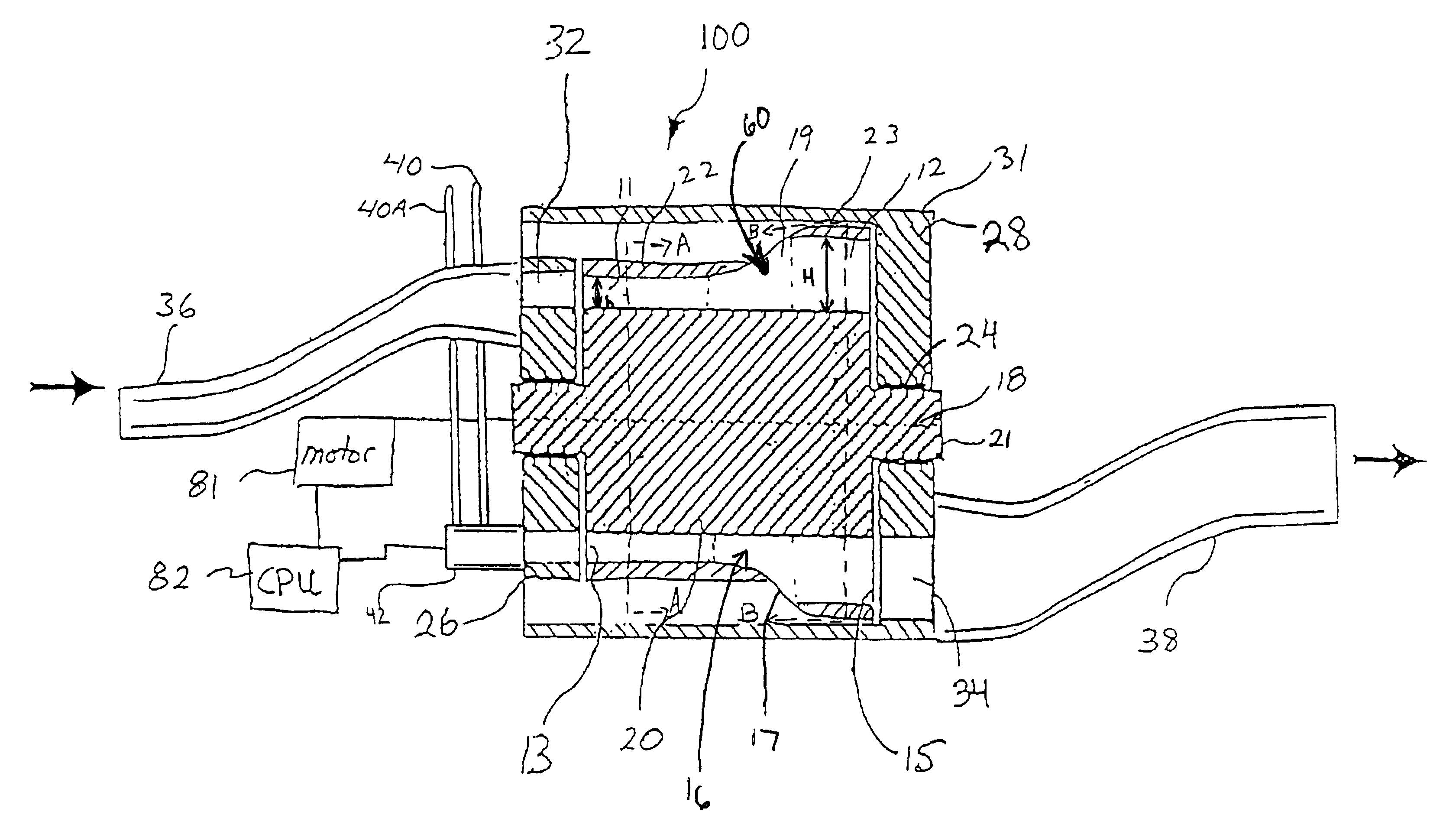
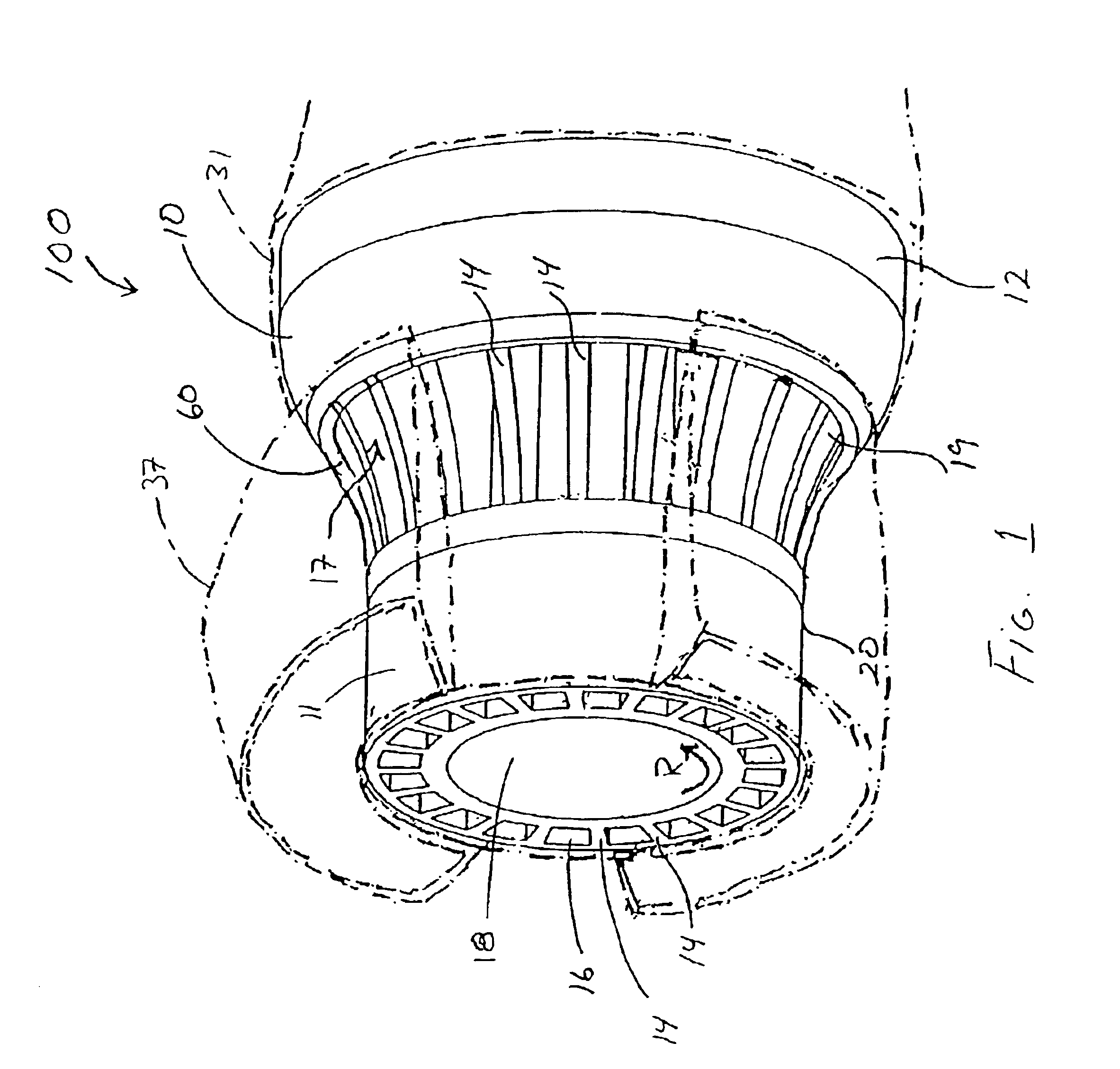
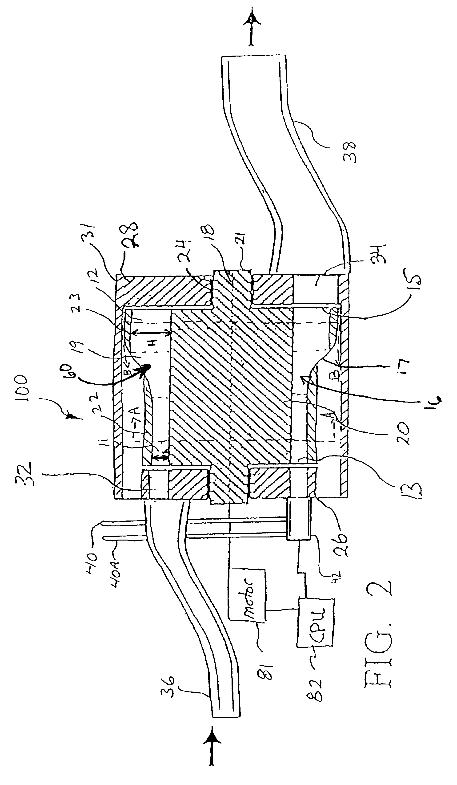
In accordance with the present invention, a wave rotor pulsed detonation engine (WRPDE) is provided having a rotary ejector for reducing excessive outflow temperature and velocity to provide a rotary-ejector-WRPDE. The engine provides improved propulsive efficiency and control of gas temperature.
A WRPDE creates motive thrust without the need for a compressed air source or a downstream turbine. The WRPDE is an on-rotor combustion device where the combustion process occurs within combustion channels of the rotor. To generate sufficient thrust, the WRPDE creates detonative combustion within the channels of the rotor. The rotary ejector of the WRPDE provides improved efficiency by transferring energy and momentum from a high speed / high-pressure flow stream to a low-pressure stream to augment thrust. This action distributes energy and momentum to a larger mass, resulting in lower overall velocity and greater propulsive efficiency and thrust. In addition, the rotary ejector may also help cool and homogenize a stream of higher temperature while providing pressure equalization. Accordingly, the present invention efficiently harnesses the energy and momentum of the detonation processes to maximize performance.
To promote the creation of detonative combustion, a plurality of separate inlet zones may be provided in the inlet port of the housing for supplying fuel and air mixtures to the inlet end of the forward combustion passages. The inlet zones are circumferentially spaced about the perimeter of the rotor so that the forward combustion passages interact with separate inlet zones sequentially. A fuel injector is provided in selected inlet zones for injecting fuel into each respective zone. Each inlet zone is capable of introducing a different combustible mixture sequentially into a given forward combustion passage as the passage rotates past the respective inlet zone. For example, a first inlet zone may be provided for providing an input of air, without fuel, into the passage to act for example as a buffer in the passage. As the passage in the rotor moves into registry with a second inlet zone, a fuel or fuel mixture may be input into the passage. Additional inlet zones may be provided for successively inputting additional fuel or fuel mixtures which may be different from other fuels or fuel concentrations, into the passage. Another inlet zone, such as the last inlet zone, may input a combustion enhancer or a mixture of fuel and a combustion enhancer into the forward combustion passage proximal to the source of ignition to enhance detonative combustion. Using successive inlet zones results in the stratification of differing concentrations of combustible material within the forward combustion passages.
Hence, in accordance with the present invention, a combustion process is provided whereby a pulsed detonation process is combined with a non-steady ejector process through the action of the rotary ejector. The varying radial height of the rotary ejector avoids the need for complex integration of a pulsed detonation device to an ejector device. At the same time, the present invention retains sufficient free design parameters to provide correct matching between the non-steady wave processes of the pulsed detonation cycle and a joiner cycle of the rotary ejector.

Problems solved by technology

Such temporal unsteadiness can pose difficulties in many applications.
The use of such mixtures creates combustion product temperatures and detonation-induced velocities that are excessive for most applications.
As a result there are several distinct problems that must be addressed in the design of pulsed detonation engines.
A first such problem is that the outflow peak temperature, mass-average temperature, peak velocity, and mass-average velocity are too high for many practical applications.
Excessive velocity and temperature in the outflow create low propulsive efficiency, limited thrust, and limited device lifetime.
In a gas generator PDE device designed to power a turbine, it is undesirable to have a non-steady or non-uniform velocity turbine flow.
In addition, high velocity jets also produce excessive noise, and high temperature jet engines may be vulnerable to thermal-signature tracking missiles.
However, these configurations often have limitations that include: the need for dedicated feed and ignition hardware for each tube; flow stagnation in multiple feed distribution exhaust collection ducts; the need for multiple high-repetition detonation initiation devices; the need for complex fast-cycling valving for purging gas, fuel, and oxidant / enrichment; and the need for many pulsing or moving components as well as many parts outside the flow path with significant weight and volume.
In addition, stationary tube PDE's have further limitations that include reduced durability based on the need for valves and bearings that transmit thrust.
In addition, the noise created by the cyclically loaded parts can pose further problems.

Method used


Image

  • Rotary ejector enhanced pulsed detonation system and method
  • Rotary ejector enhanced pulsed detonation system and method
  • Rotary ejector enhanced pulsed detonation system and method

Examples


examples

Computational Results

Preliminary analysis may be performed using a quasi one-dimensional, uniform-grid numerical model of a pulsed combustion process. It employs a code originally developed and validated for wave rotors with non-reacting flow in uniform passages, and later extended to reacting flow, and non-uniform passages.

The code uses an Euler solver to integrate the governing equations of mass, momentum, energy, and species. It has the capability to accommodate multiple port boundary conditions at each end per cycle. It can model mixing, opening time and viscous losses, as well as those losses from leakage, heat transfer, and flow turning effects. It has now been modified to allow mass addition at any location and include the associated momentum and energy sources due to the presence of such mass sources. The governing equations are integrated for any specified time with cyclic boundary conditions. Inlet conditions are specified by appropriate stagnation quantities, and an outfl...


PUM


Abstract

A rotary ejector enhanced wave rotor pulsed detonation (WRPDE) engine and method are provided. The rotary-ejector-WRPDE includes a housing, one or more inlet ports in the housing, and a rotor mounted within the housing. The rotor includes a plurality of shrouded forward combustion passages in which detonative combustion occurs. Each forward combustion passage has an inlet end for communication with the inlet port. The rotor also includes a plurality of rear combustion passages which are in gaseous communication with the forward combustion passages. The rotor further includes a plurality of transitional combustion passages which join the forward combustion passages to the rear combustion passages and communicate with a source of bypass gas to provide a rotary ejector.

Description

FIELD OF THE INVENTIONThe present invention relates generally to a rotary ejector for use with a wave rotor pulsed detonative engine.BACKGROUND OF THE INVENTIONPulsed detonation engines (PDE's) are non-steady combustion devices that typically produce intermittent high-momentum jets of exhaust separated by longer periods of dribbling or no outflow. Such temporal unsteadiness can pose difficulties in many applications. In addition, reliable detonation in such engines requires the use of highly energetic near-stoichiometric mixtures. The use of such mixtures creates combustion product temperatures and detonation-induced velocities that are excessive for most applications. As a result there are several distinct problems that must be addressed in the design of pulsed detonation engines. The severity of each problem depends on the particular PDE configuration, combustion method, and application, and in particular, on whether the output flow is used directly for jet propulsion or is used t...

Claims


Application Information

Patent Timeline
Patent Type & Authority Patents(United States)
IPC IPC(8): F02C3/00F02B53/00F02C3/02F02BF02K7/02F04F13/00F04F99/00
CPCF02C3/02F04F13/00F02K7/02
Inventor NALIM, MOHAMED RAZI
Owner ADVANCED RES TECH INST
Learn More