Battery Pack and Electric Work Vehicle

a battery pack and work vehicle technology, applied in the direction of battery/fuel cell control arrangement, cell components, battery/cell components, etc., can solve the problem of easy choke up of the cooling air passage with foreign matter, and achieve the effect of reducing the number of battery modules and ensuring uniform temperature within the casing

Active Publication Date: 2016-10-06
KUBOTA LTD
View PDF4 Cites 17 Cited by
  • Summary
  • Abstract
  • Description
  • Claims
  • Application Information

AI Technical Summary

Benefits of technology

[0009]With the above arrangement, the battery unit and the circulation fan are housed tightly in a single casing. This prevents entry of foreign matters from the outside by air circulation within the casing caused by the circulation fan, and by restriction against entry of ambient air by tight closing of the casing; and yet maintains uniform temperature within the casing. The air guide is provided to achieve the uniform temperature within the casing more effectively. The air guide functions to properly orient the cooling air generated by the circulation fan to provide uniform temperature distribution over the battery unit. Such a uniform temperature distribution over the battery unit results in efficient use of the battery modules.
[0010]It should be noted that the term “tightly housing” should not be construed in a narrow meaning that the casing is maintained in a perfect airtight condition, but should be construed in a broader meaning that the casing may be closed less tightly to the extent that the amount of ambient air introduced into the casing is sufficiently reduced to prevent the ambient temperature from being easily equilibrated with the inner space temperature.
[0011]It should be noted that the present invention is also intended to cover an electric work vehicle equipped with the above battery pack. More particularly, the electric work vehicle according to the present invention includes a battery pack, rear wheels driven by power supply from the battery pack, and an work implement disposed forward of a central axis of the rear wheels and driven by power supply from the battery pack, in which the battery pack is disposed rearward from the central axis of the rear wheels. Further, the battery pack includes a battery unit, a casing for tightly housing the battery unit, a circulation fan mounted in an inner space of the casing, and an air guide provided in the casing to direct cooling air produced by the circulation fan to the battery unit. Thus, such an electric work vehicle can enjoy all the advantages brought by the above-described battery pack.

Problems solved by technology

As a result, a cooling air passage is easily choked up with such foreign matters.

Method used


Image

  • Battery Pack and Electric Work Vehicle
  • Battery Pack and Electric Work Vehicle
  • Battery Pack and Electric Work Vehicle

Examples


Embodiment Construction

[0022]The particulars shown herein are by way of example and for purposes of illustrative discussion of the embodiments of the present invention only and are presented in the cause of providing what is believed to be the most useful and readily understood description of the principles and conceptual aspects of the present invention. In this regard, no attempt is made to show structural details of the present invention in more detail than is necessary for the fundamental understanding of the present invention, and the description taken with the drawings making apparent to those skilled in the art how the forms of the present invention may be embodied in practice.

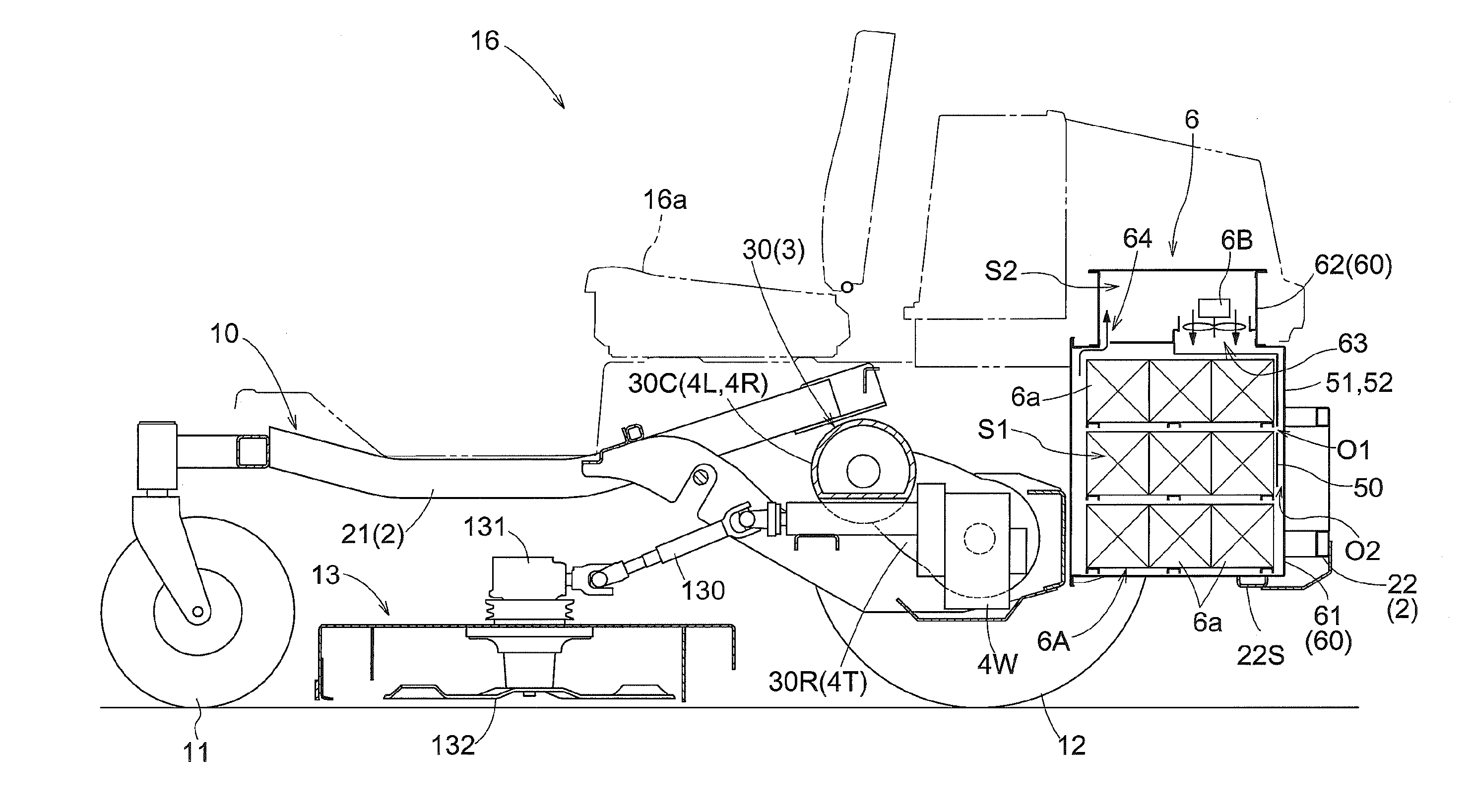
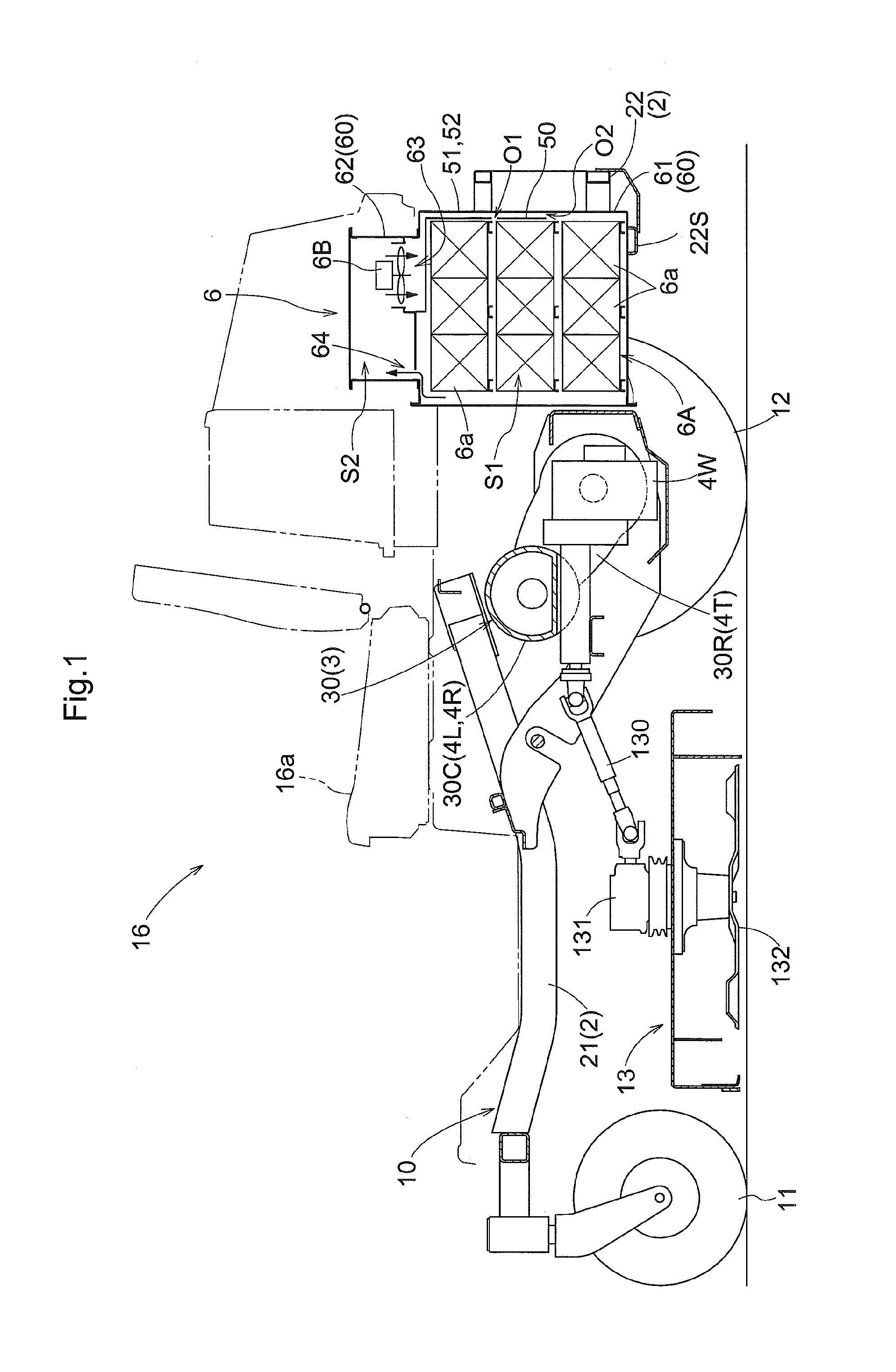
[0023]Prior to detailed description of a battery pack and an electric work vehicle loaded with the battery pack according to one specific embodiment of the present invention, a fundamental arrangement of the battery pack will be described first with reference to FIG. 1.

[0024]While shown as disassembled in FIG. 1, the battery ...


PUM

PropertyMeasurementUnit
temperatureaaaaaaaaaa
temperature distributionaaaaaaaaaa
electric poweraaaaaaaaaa

Abstract

A battery pack (6) for an electric work vehicle includes a battery unit (6A), a casing (60) for tightly housing the battery unit (6A), a circulation fan (6B) mounted in an inner space of the casing (60), and an air guide (50) provided in the casing (60) to direct cooling air produced by the circulation fan (6B) to the battery unit (6A).

Description

CROSS REFERENCE TO RELATED APPLICATION[0001]This application claims priority to Japanese Patent Application No. 2015-076062 filed Apr. 2, 2015, the disclosure of which is hereby incorporated in its entirety by reference.BACKGROUND OF THE INVENTION[0002]1. Field of the Invention[0003]The present invention relates to a battery pack for an electric work vehicle propelling and performing work operation with an electric motor, and an electric work vehicle loaded with the battery pack.[0004]2. Related Art of the Invention[0005]Electric vehicles driven by rotary power from electric motors have been widespread in the automobile filed. Such an electric vehicle is loaded with a battery as a power source for the electric motor. In many cases, the battery includes a cooling system for keeping the battery temperature at a proper level to maintain the performance of the battery. An example of conventional battery packs for vehicles is disclosed in Japanese Unexamined Patent Application Publicatio...

Claims


Application Information

Patent Timeline
Patent Type & Authority Applications(United States)
IPC IPC(8): H01M2/02H01M10/625H01M10/6563A01D34/78A01D34/64B60L11/18B60K1/04H01M10/613H01M10/6566H01M50/209H01M50/249H01M50/262
CPCH01M2/0242H01M10/613H01M10/625H01M10/6563H01M10/6566B60K2001/0416B60L11/1874B60K1/04A01D34/78H01M2220/20A01D34/64H01M10/6551H01M10/6557B60L2200/40B60L2240/545B60L58/26B60L50/66B60L50/64Y02T10/70Y02E60/10H01M50/249H01M50/209H01M50/262
Inventor ITO, HIROKAZUKOIKE, KAZUO
Owner KUBOTA LTD
Why Eureka
Try Eureka